


Engine 1.25 / 1.4 l
Since it is impossible to take into account all options when removing, it is recommended to mark each wire with adhesive tape before removing. Pay attention to the instructions for the 1.3L engine, diesel and Ford KA model at the end of the section.
Necessary fixtures and equipment:
- Puller for tie rod joints.
- Lift with trailer or mounting stand.
Removing
Remove the battery and battery console.
Attention: Disconnecting the battery will erase the data from the electronic memory units. See instructions in chapter «electrical equipment».
Remove the air filter and air hose from the throttle valve fitting.
Raise and support the car, remove the lower casing of the engine compartment.
Drain the oil from the gearbox.
Engage fourth gear on the gearbox.
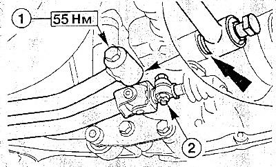
Loosen clamping bolt (2) and pull the shift rod off the shift shaft. Unscrew the bolt and remove the stabilizer (1), noting the installation position of the washer to avoid errors during reinstallation
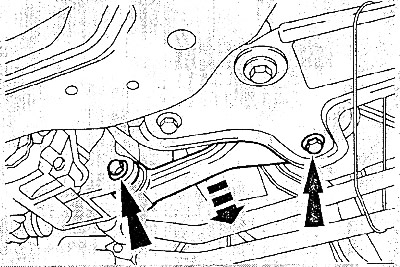
Unscrew the bolts and remove the spacer between the engine and the mount from the bottom of the body.
Remove both drive shafts.
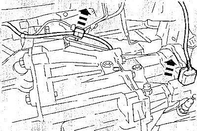
Press the wire clamp out of the mounting on the gearbox. Disconnect the reverse light switch connector.
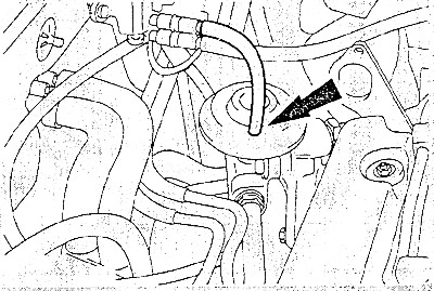
Pull the vacuum hose off the EGR valve (on the exhaust manifold).
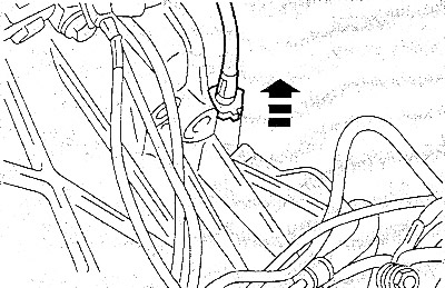
Unscrew the speedometer drive shaft/speed sensor from the gearbox.
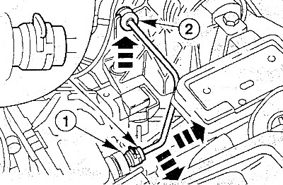
Disconnect the hydraulic line from the slave cylinder on the gearbox. To do this, pull the fastening bracket out of the connection (1) and pull the wire. Push the wire out of the guide (2).
Attention: Use a cloth to collect the escaping brake fluid. Rules for handling brake fluid are described in chapter «Brake system».
Close the open pipeline with a plug or cap to prevent dirt from getting inside.
Attach the engine with a rope or chain to a hoist.
Raise the engine so that the engine mounts are unloaded.
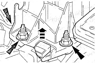
Unscrew the bolts securing the left support of the power unit (from the gearbox side).
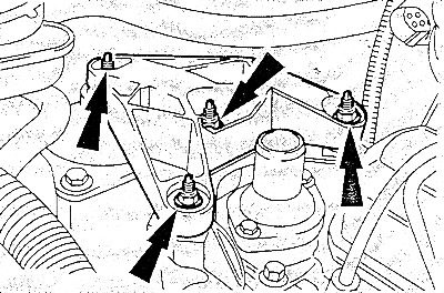
Loosen the bolts/nuts securing the right engine mount.
Carefully lower the power unit (engine/gearbox) about 10 cm.
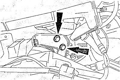
Remove the mounting bolts from the throttle body.
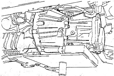
Lightly support the gearbox with a wooden jack.
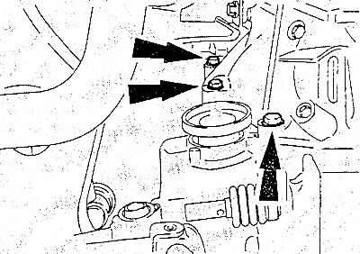
Remove the three front gearbox flange bolts.
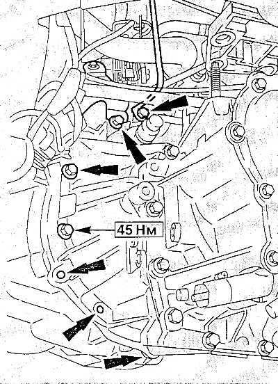
Unscrew the rear bolts of the gearbox flange - this will also remove the wire «masses» gearboxes.
Raise the gearbox slightly and press the pry bar away from the engine.
Carefully remove gearbox.
Installation
Check clutch before installation.
Check the ease of movement of the clutch release bearing. If, before removing the gearbox, when you press the clutch pedal, there was noise from the operation of the release bearing, then you need to replace it.
Clean gearbox input shaft splines and lightly lubricate them with molybdenum based grease. Do not apply too much grease, otherwise it will be squeezed out on the clutch surfaces, which will cause the clutch to work poorly.
Check whether both engine/gearbox alignment pins are present in the cylinder block, insert if necessary. Align intermediate plate with both pins.
Raise gearbox and insert horizontally into clutch. If during installation the input shaft of the gearbox does not fit into the clutch disc, turn the input shaft slightly by turning the flange for the drive shaft by hand.
Insert the bolts connecting the engine and gearbox and tighten them one by one to 45 Nm. Strengthen the wire «masses» on the top bolt of the gearbox flange.
Screw the speedometer cable/speed sensor into the transmission.
Carefully lift the power unit into the engine compartment while guiding the engine correctly.
Install the right and left engine mounts with new nuts.
Attention: Nuts on the left engine mount (from the gearbox side) hand tighten 5-6 turns, but do not tighten.
Tighten nuts on right engine mount to 70 Nm. О Disconnect the engine from the hoist or winch.
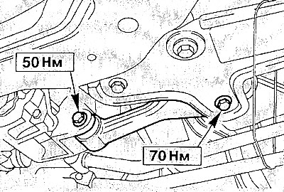
Install the spacer and tighten its bolt on the mounting to 70 Nm, on the gearbox to 50 Nm.
Align the engine mounts by rocking the engine vigorously so that they sit without tension.
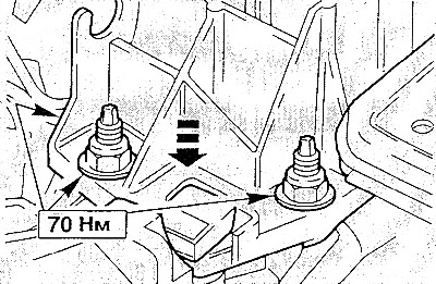
Now tighten the nuts on the left engine mount (from the gearbox side) torque 70 Nm.
Install holder (fastening) to the throttle body. Connect the hose to the EGR valve and the plug to the transmission reversing light switch.
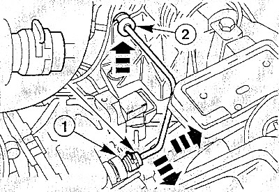
Install the hydraulic line to the clutch slave cylinder. To do this, pull out the fastening bracket in the connection (1), push in the pipeline and install again" bracket. Press the pipeline into the guide (2).
Bleed the air from the hydraulic clutch.
Install stabilizer with washer on gearbox housing and tighten bolt to 55 Nm.
Clean the connection points of the shift rod and the shift shaft and connect the parts.
Adjust the shift mechanism.
Set Both Leads (drive) shaft with new circlips.
Install the battery tray, tightening the three mounting bolts to 25 Nm.
Install the battery.
Set the clock, enter the necessary codes.
Install the air filter.
Check the oil level in the gearbox and engine and top up if necessary.
Start the engine and warm it up in motion to operating temperature. Check hose connections for tightness.
Install the lower engine cover.
Special for 1.3L engine
Remove starter.
Remove the front exhaust pipe.
Hook up the engine and loosen the engine mounts.
Note: Engine mounts on Ford KA models are shown at the beginning of the chapter «Engine».
Especially for diesel engine
Remove starter.
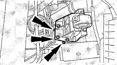
Slightly lower the engine/gearbox assembly using a hoist and remove the engine support bracket.
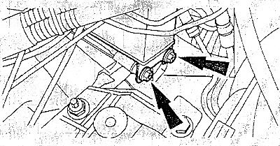
Loosen the upper resonator mounting bolts.
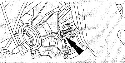
Loosen the lower resonator mounting bolt.