
Removing
Drain the gearbox oil.
Remove the brake caliper.
Remove the brake disc.
Remove the tie rod end ball joint.
Remove the anti-roll bar.
Loosen the mounting bolts and remove the ball joint of the front lower arm (rear end).
Remove the ball joint of the front lower arm (front end).
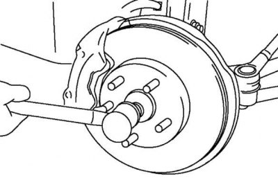
Pic. 3.140. Installing a spare nut on the drive shaft
Install the spare nut on the drive shaft so that the nut is flush with the end of the drive shaft (pic. 3.140).
Hit the nut with a copper mallet to loosen the drive shaft from the wheel hub.
Separate the drive shaft from the wheel hub.
Attention! Sharp edges on the drive shaft can cut or pierce the oil seal. Be careful when separating the drive shaft from the gearbox.
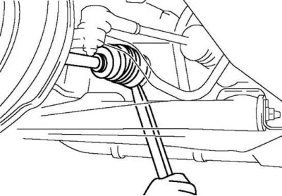
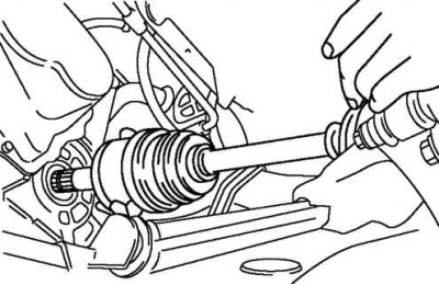
Pic. 3.141. Removing the left drive shaft from the gearbox using a rod
Separate the left power shaft from a transmission, using as the lever the core inserted between the hinge and a transmission, as is shown in drawing 3.141.
Install the special tool to hold the side gears after removing the connecting shaft to the gearbox.
Installation
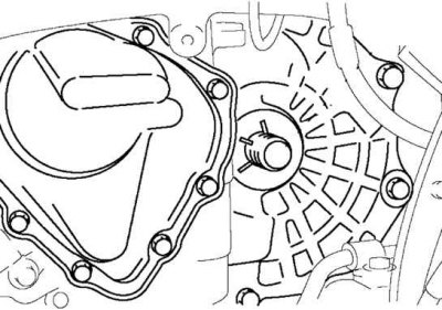
Pic. 3.142. Installation of a special tool for holding side gears
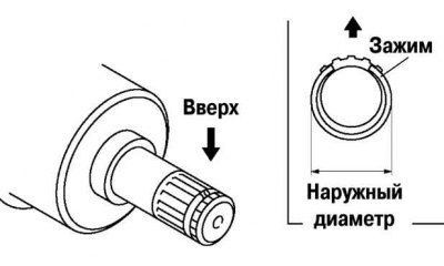
Pic. 3.143. Installing a new clamp on the connecting shaft
Install a new clamp on the connecting shaft with the slit facing up. Make sure the clamp diameter is not too large (pic. 3.143).
After installation, measure the outside diameter.
If it differs from the norm, repeat the installation using a new clamp.
Maximum outer diameter: 31.2 mm.
Insert the drive shaft into the wheel hub.
Pic. 3.144. Installing the drive shaft
Apply gear oil to the seal lip (pic. 3.144).
Insert the drive shaft into the gearbox.
After installation, pull the inboard joint housing towards you to ensure that the drive shaft is secure.
Install other components in the reverse order of removal.