
MazBook.ru
English Русский
Български
Беларускі
Український
Српски
Hrvatski
Română
Polski
Slovenský
Magyar
• Bookmark • Sitemap • Contacts •   
Cars Opel Cars Ford Cars Volkswagen Cars Audi Cars Kia Cars Renault Cars Peugeot


Familia Capella Mazda3 Mazda6 CX-? Others Articles
Mazda6 GG (2002-2008)

Removal and installation the drive shaft (manual transmission) (Mazda 6 GG)

  • Home
  • Mazda 6
  • Mazda6 GG (2002-2008)
  • Transmission
  • Drive shafts and hubs
  • Removal and installation the drive shaft (manual transmission)
0
Contents: Removal ⇓ Installation ⇓
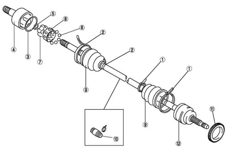
Fig. 3.159. Front drive shaft components: 1 – cover clamp (from the wheel side); 2 – cover clamp…

Fig. 3.159. Front drive shaft components: 1 – cover clamp (from the wheel side); 2 – cover clamp (from the gearbox side); 3 – clamp; 4 – hinge housing; 5 – retaining ring; 6 – balls; 7 – clip; 8 – separator; 9 – case; 10 – dynamic damper; 11 – Anti-lock brake system sensor rotor; 12 – shaft and ball joint


The front drive shaft components are shown in Fig. 3.159.

Removal
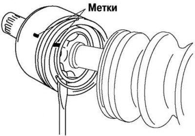


Fig. 3.160. Marking the joint housing and drive shaft

Fig. 3.160. Marking the joint housing and drive shaft


Mark the hinge housing and shaft for subsequent assembly (fig. 3.160).

Attention! Apply markings with paint; do not use a hammer drill.


Remove the clamp.

Mark the clip and separator.

Remove the snap ring using snap ring pliers.
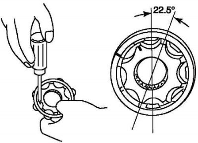
Fig. 3.161. Removing the separator

Fig. 3.161. Removing the separator


Rotate the separator approximately 30° and separate the separator and balls from the cage (fig. 3.161).

Installation
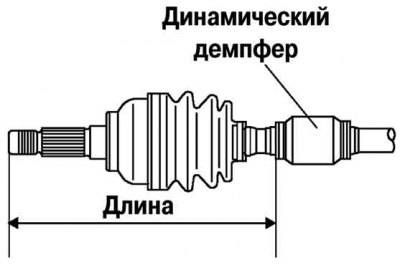


Fig. 3.162. Installing a dynamic damper

Fig. 3.162. Installing a dynamic damper


Install the dynamic damper as shown in Figure 3.162.

Standard length: 334.7–340.7 mm.

Install the new boot clamp onto the dynamic damper.

Fill the case (from the wheel side) consistent lubricant.

Note: The wheel side and gearbox side covers are different.


Warning! Do not touch the grease with your hands. Apply grease from the tube, do not allow contaminants to enter the case.


Attention! Amount of grease: 90–110 g (L8, LF left side), 105–125 g (L8, LF right side and L3)


Install the cover without removing the adhesive tape that was wrapped around the shaft splines during disassembly.

Remove the tape.
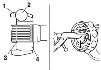
Fig. 3.163. Installing the separator and balls in the cage: 1 – separator; 2 – balls; 3 – groove of…

Fig. 3.163. Installing the separator and balls in the cage: 1 – separator; 2 – balls; 3 – groove of the retaining ring; 4 – clip


Align the marks and install the balls and separator into the cage in the direction shown in Figure 3.163.

Caution! Install the separator with the chamfer facing the groove of the retaining ring. If installed incorrectly, the drive shaft may come apart while driving.


Install a new snap ring.

Fill the hinge housing and boot (from the gearbox side) consistent lubricant.

Amount of grease: 105-125 g (L8, LF left side), 120–140 g (L8, LF right side and L3).

Align the marks and install the housing on the shaft.

Install the new clamp.

Install the cover.

Set the drive shaft to standard length.

Release the air from the covers by lifting the edges of the smaller ends of the covers with a screwdriver wrapped in a cloth.

Original version of the article on the website (MazBook.ru)

Make sure the drive shaft length is within specifications.

Standard length, mm
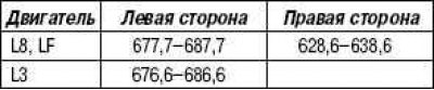


Standard length, mm
This article is available at: russian, bulgarian, belarusian, ukrainian, serbian, croatian, romanian, polish, slovak, hungarian
This text was checked by: Evdokia Filimonova
Share with friends on social networks:

Previous
Mazda6 GG » Drive shafts and hubs
Next

Removal and installation the front drive shaft (automatic…
Front Drive Shaft Components (Automatic Transmission)
Removal and installation the front drive shaft (manual transmission)
Preliminary check of the drive shaft (manual transmission)
Front Drive Components (Manual Transmission)
More articles on repairing other Mazda models
Detailed technical characteristics of the manual transmission Mazda Familia 5 (1985-1989)
Inspection of transmission output shaft seals and drive shaft boots Mazda Capella 3 (1982-1992, petrol)
Removal and installation the drive shaft (with manual transmission) Mazda3 BK (2003-2009)
Manual transmission — technical data Mazda CX-5KE (2012-2017)
Manual transmission: checking the oil level Mazda 121 (3) (1996-2003)
Link in different formats to this article
Comments and feedback from visitors
No comments yet


How much will 11 + 31 ?


Mazda6 GG (2002-2008) 
  • User manual
  • Vehicle description
  • Keys, locks and alarms
  • Controls and instruments
  • Air conditioning and heater
  • Seat adjustment
  • Security systems
  • Driving and operation
  • Faults en route
  • Maintenance
  • Power unit
  • Engine device
  • Engine repair
  • Lubrication system
  • Cooling system
  • Fuel system
  • Exhaust system
  • Electrical equipment of engines
  • Control system
  • Transmission
  • Clutch
  • Mechanical gearbox
  • Automatic gearbox
  • Drive shafts and hubs
  • Chassis
  • Suspension and wheels
  • Steering
  • Brake system
  • Body
  • Exterior (external elements)
  • Interior (internal elements)
  • Doors and windows
  • Air conditioning and heater
  • Electrical equipment
  • Equipment and devices
  • Power devices
  • Lighting system
  • Windshield wipers and washers
MazBook.ru © 2018–2026 · Mobile version · Articles and news · Sitemap: EN BG BY UA RS HR RO PL SK HU · Feedback · Site search · Add to bookmarks Familia 5 (BF) · Familia 6 (BG) · Capella 3 (GC) · Capella 3 and 4 (GC) · Capella 4 (GD) · Capella 5 (GE) · Capella 6 (GF) · Mazda3 BK · Mazda6 GG · CX-5KE · Mazda 121 (3) · Mazda BT-50 (1) ·
By continuing to use the site, you agree to the use of cookies 🔐