


Contents: Removal ⇓ Installation ⇓
Removal
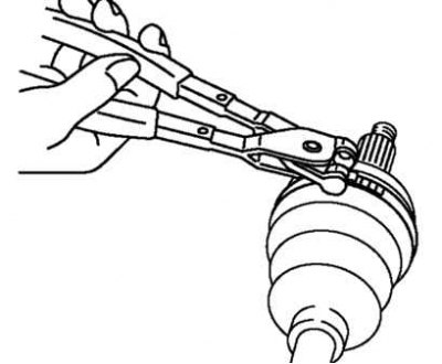
Fig. 3.146. Removing the cover clamp (from the wheel side) with special pliers
Remove the cover clamp (from the wheel side) with special pliers, as shown in Figure 3.146.
Use a screwdriver to bend back the clamp's locking clips.
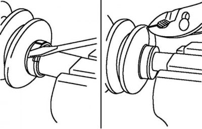
Fig. 3.147. Removing the cover clamp (from the gearbox side)
Pull out the end of the clamp (fig. 3.147).
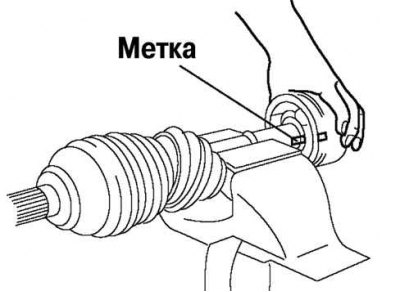
Fig. 3.148. Marking the joint housing and drive shaft
Mark the hinge housing and shaft for subsequent assembly (fig. 3.148).
Remove the hinge housing.
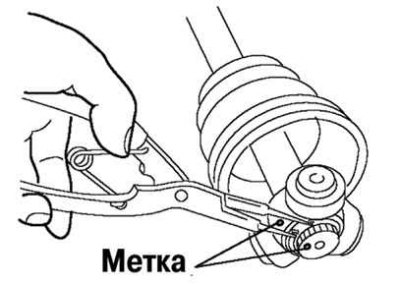
Fig. 3.149. Marking the drive shaft and tripod
Mark the shaft and tripod for subsequent assembly (fig. 3.149).
Remove the snap ring using snap ring pliers.
Remove the tripod joint from the shaft.
Caution: Do not hit the tripod with a hammer.
Note: The wheel side boot should not be removed unless the boot, shaft or ball joint is being replaced. Do not remove the tape until the boot is assembled.
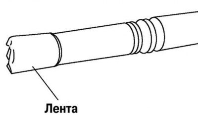
Fig. 3.150. Protection of drive shaft splines
Wrap the shaft splines with tape (fig. 3.150).
Remove the cover.
Note: Do not remove the ABS sensor rotor (cars with anti-lock braking system), unless required. Do not reuse a removed sensor rotor.
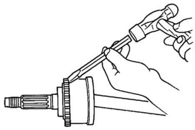
Fig. 3.151. Removing the ABS sensor rotor from the drive shaft
Knock the ABS sensor rotor off the drive shaft with a chisel (fig. 3.151).
Remove the dynamic damper.
Installation
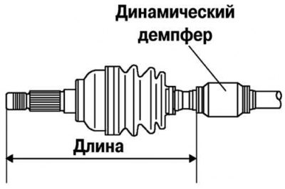
Fig. 3.152. Installing a dynamic damper
Install the dynamic damper as shown in Figure 3.152.
Standard length: 334.7–340.7 mm.
Install the new boot clamp onto the dynamic damper.
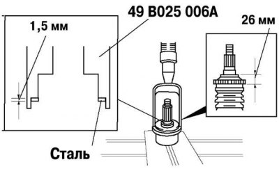
Fig. 3.153. Pressing a new ABS sensor rotor onto the drive shaft
Install the new ABS sensor rotor onto the drive shaft and press it in place using special tools (fig. 3.153).
Fill the case (from the wheel side) consistent lubricant.
Note: The wheel side and gearbox side covers are different.
Warning! Do not touch the grease with your hands. Apply grease from the tube, do not allow contaminants to enter the case.
Attention! Amount of consistent grease: 90–110 g.
Install the cover without removing the adhesive tape that was wrapped around the shaft splines during disassembly.
Remove the tape.
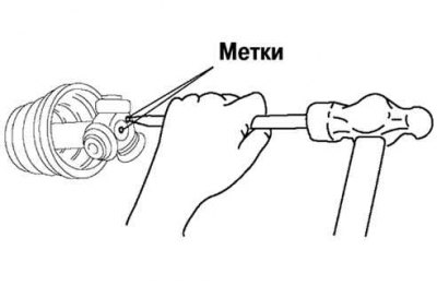
Fig. 3.154. Tripod installation
Align the marks made during removal and install the tripod using a rod and hammer (fig. 3.154).
Install a new snap ring using snap ring pliers.
For details, see the website MAZbook.ru
Caution: Make sure the snap ring is seated in the groove of the shaft.
Fill the hinge housing and boot (from the gearbox side) consistent lubricant.
Amount of grease: 195–215 g.
Install the hinge housing.
Set the drive shaft to standard length.
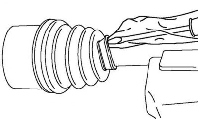
Fig. 3.155. Removing air from the covers using a screwdriver
Release the air from the covers by lifting the edges of the smaller ends of the covers with a screwdriver wrapped in a cloth (fig. 3.155).
Caution! Avoid leakage of grease. Do not damage the covers.
Make sure the drive shaft length is within specifications.
Bend the clamp in the direction opposite to the direction of rotation of the drive shaft when the vehicle is moving forward, and use pliers to tighten the clamp securely.
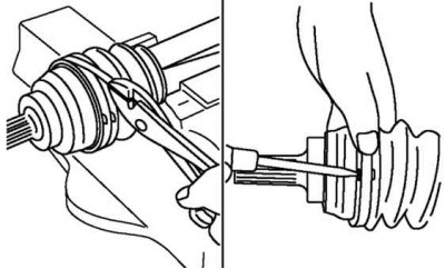
Fig. 3.156. Installing the cover clamp (from the gearbox side)
Lock the end of the clamp by bending the locking clips (fig. 3.156).
Caution: Install the clamp securely into the groove.
Adjust the gap A
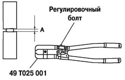
Fig. 3.157. Adjusting the gap A of the cover (from the wheel side)
by rotating the adjusting bolt of a special device (fig. 3.157).
Gap A: 2.9 mm.
Press the small clamp of the boot on the wheel side using a special tool. Check that the gap IN - within normal limits (fig. 3.158).
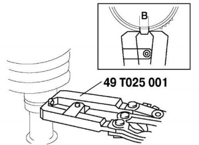
Fig. 3.158. Adjusting the gap B of the cover (from the wheel side)
If there is a gap IN more than the norm, reduce the gap of the special device and compress the cover again.
If there is a gap IN less than the norm, replace the cover clamp, increase the gap of the special device and squeeze the new cover.
Gap IN: 2.4–2.8 mm.
Make sure that the boot clamp does not protrude from the boot clamp installation area.
If so, replace the boot clamp and reinstall.
Fill the boot with the grease from the repair kit.
Adjust the clearance B by turning the adjusting bolt of the special tool.
Gap IN: 3.2 mm.
Make sure that the cover clamp does not protrude from the installation area.