


Car air conditioner and heater Mazda 6 (GG)

Air Conditioner and Heater Specifications
Fig. 8.77. Air conditioning and heater of Mazda 6: 1 – fan unit; 2 – air filter; 3 – air conditioning system unit; 4 – Air conditioning compressor; 5 – evaporator; 6 –...
Fig. 8.77. Air conditioning and heater of Mazda 6: 1 – fan unit; 2 – air filter; 3 – air conditioning system unit; 4 – Air conditioning compressor; 5 – evaporator; 6 –...

Air filter
The car is equipped with an air filter that can deodorize the air and clean it from pollen and dust. The air filter consists of a deodorizer surrounded by a dust filter....
The car is equipped with an air filter that can deodorize the air and clean it from pollen and dust. The air filter consists of a deodorizer surrounded by a dust filter....
Air conditioning system unit
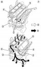
The air conditioning system unit combines cooling and heating units. Operation of the heater control flap (Fig. 8.79). Fig. 8.79. Operation of the heater control flap: 1...
The air conditioning system unit combines cooling and heating units. Operation of the heater control flap (Fig. 8.79). Fig. 8.79. Operation of the heater control flap: 1...

Air conditioner evaporator
A new type of evaporator is used, which combines a multi-flow evaporator (consisting of a condensation element and a supercooling element) and a gas-liquid separator...
A new type of evaporator is used, which combines a multi-flow evaporator (consisting of a condensation element and a supercooling element) and a gas-liquid separator...

Expansion valve
The expansion valve provides a sharp reduction in the pressure of the liquid refrigerant. In this case, the refrigerant is atomized, which facilitates the evaporation...
The expansion valve provides a sharp reduction in the pressure of the liquid refrigerant. In this case, the refrigerant is atomized, which facilitates the evaporation...

Air conditioner condenser
A condenser with additional cooling is used. This is a multi-flow condenser, which is equipped with an additional cooling element and is combined with a...
A condenser with additional cooling is used. This is a multi-flow condenser, which is equipped with an additional cooling element and is combined with a...
Air conditioning control system
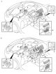
Fig. 8.84. Air conditioner control system: 1 – Manual air conditioning system; 2 – Automatic air conditioning system; 3 – air intake actuator; 4 – heater control...
Fig. 8.84. Air conditioner control system: 1 – Manual air conditioning system; 2 – Automatic air conditioning system; 3 – air intake actuator; 4 – heater control...

Air conditioning control unit
Manual air conditioning system The air conditioning control unit with cable drive is used in the air conditioning system with manual control. The fan mode controller,...
Manual air conditioning system The air conditioning control unit with cable drive is used in the air conditioning system with manual control. The fan mode controller,...

Checking the heater radiator
Remove the air conditioning unit. Remove the air conditioning unit heater radiator. Check for cracks, damage and coolant leaks. If any faults are detected, replace the...
Remove the air conditioning unit. Remove the air conditioning unit heater radiator. Check for cracks, damage and coolant leaks. If any faults are detected, replace the...

Removal and installation the rear air duct
Turn over the front floor covering. Fig. 8.88. Rear air duct: 1 – rear air duct (right side); 2 – rear air duct (left side) Remove the rear air duct (right side, see...
Turn over the front floor covering. Fig. 8.88. Rear air duct: 1 – rear air duct (right side); 2 – rear air duct (left side) Remove the rear air duct (right side, see...

Removal and installation the air conditioning compressor
Disconnect the negative cable from the battery. Discharge the refrigerant. Remove the right mudguard and splash guard. Loosen the drive belt tension and remove the belt....
Disconnect the negative cable from the battery. Discharge the refrigerant. Remove the right mudguard and splash guard. Loosen the drive belt tension and remove the belt....

Disassembly and assembly of the overrunning clutch
Fig. 8.90. Disassembling the overrunning clutch: 1 – bolt; 2 – pressure plate; 3 – gasket; 4 – retaining ring; 5 – Air conditioning compressor pulley; 6 – screw; 7 –...
Fig. 8.90. Disassembling the overrunning clutch: 1 – bolt; 2 – pressure plate; 3 – gasket; 4 – retaining ring; 5 – Air conditioning compressor pulley; 6 – screw; 7 –...

Removal the overrunning clutch bolt
Fig. 8.91. Removing the overrunning clutch bolt When removing and installing the bolt, hold the pressure plate as shown in Figure 8.91. When installing a new air...
Fig. 8.91. Removing the overrunning clutch bolt When removing and installing the bolt, hold the pressure plate as shown in Figure 8.91. When installing a new air...

Adjusting the overrunning clutch
Fig. 8.94. Measuring the circumferential clearance between the pressure plate and the compressor pulley Measure the circumferential clearance between the pressure plate...
Fig. 8.94. Measuring the circumferential clearance between the pressure plate and the compressor pulley Measure the circumferential clearance between the pressure plate...

Checking the overrunning clutch
Fig. 8.96. Schematic diagram of voltage supply from the positive terminal of the battery to terminal A of the magnetic clutch Apply voltage from the positive terminal of...
Fig. 8.96. Schematic diagram of voltage supply from the positive terminal of the battery to terminal A of the magnetic clutch Apply voltage from the positive terminal of...
This section is available on: russian, bulgarian, belarusian, ukrainian, serbian, croatian, romanian, polish, slovak, hungarian
More sections on repairs of other Mazda models
• Power unit: Air conditioner Mazda Capella 5 (1991-1997)
• Power unit: Air conditioner Mazda Capella 5 (1991-1997)
Link in different formats to this section
TEXTHTMLBB Code
- User manual
- Vehicle description
- Keys, locks and alarms
- Controls and instruments
- Air conditioning and heater
- Seat adjustment
- Security systems
- Driving and operation
- Faults en route
- Maintenance
- Power unit
- Engine device
- Engine repair
- Lubrication system
- Cooling system
- Fuel system
- Exhaust system
- Electrical equipment of engines
- Control system
- Transmission
- Clutch
- Mechanical gearbox
- Automatic gearbox
- Drive shafts and hubs
- Chassis
- Suspension and wheels
- Steering
- Brake system
- Body
- Exterior (external elements)
- Interior (internal elements)
- Doors and windows
- Air conditioning and heater
- Electrical equipment
- Equipment and devices
- Power devices
- Lighting system
- Windshield wipers and washers