


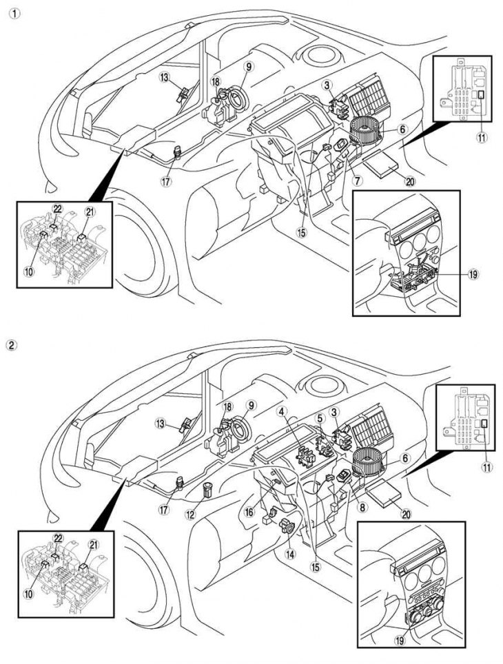
Fig. 8.84. Air conditioner control system: 1 – Manual air conditioning system; 2 – Automatic air conditioning system; 3 – air intake actuator; 4 – heater control actuator; 5 – actuator for controlling the blowing mode; 6 – fan electric motor; 7 – resistor; 8 – Automatic MOS FET; 9 – magnetic clutch; 10 – Air conditioning system relay; 11 – fan relay; 12 – solar radiation sensor; 13 – ambient air temperature sensor; 14 – cabin air temperature sensor; 15 – evaporator temperature sensor; 16 – coolant temperature sensor; 17 – refrigerant pressure sensor; 18 – heat protector; 19 – climate control unit; 20 – PCM block; 21 – TNS relay; 22 – Rear window heater relay
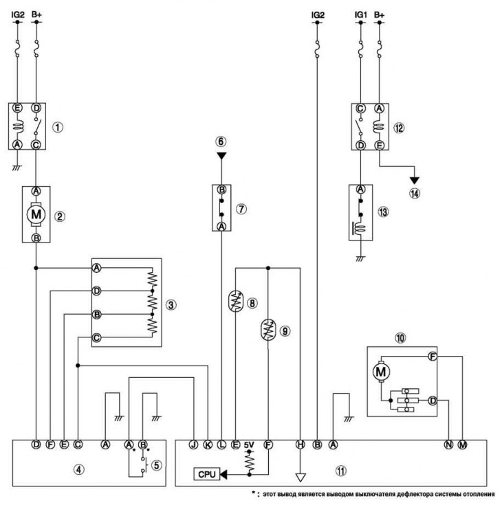
Fig. 8.85. Wiring diagram of the air conditioner control system: 1 – fan relay; 2 – fan electric motor; 3 – resistor; 4 – air conditioning control unit; 5 – heating system deflector switch; 6 – from the PCM block; 7 – refrigerant pressure sensor; 8 – ambient air temperature sensor; 9 – evaporator temperature sensor; 10 – air intake actuator; 11 – central panel; 12 – Air conditioning system relay; 13 – magnetic clutch; 14 – to the PCM block
The air conditioner control system is shown in Fig. 8.84