


Operation of the heater control flap (Fig. 8.79).
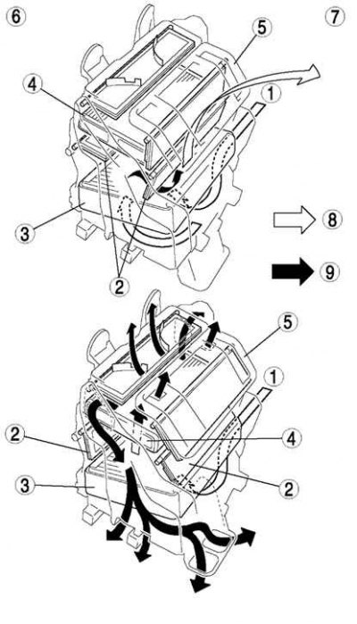
Fig. 8.79. Operation of the heater control flap: 1 – air flow; 2 – heater control flap; 3 – evaporator; 4 – heater radiator; 5 – air conditioning system unit; 6 - cold; 7 - hot; 8 – cold air; 9 – warm air
The heater control flap, installed in the air conditioning unit, controls the supply of hot or cold air, depending on the position of the temperature regulator. Air temperature is controlled by changing the distribution of air flows.
Operation of the blower control flap (Fig. 8.80).
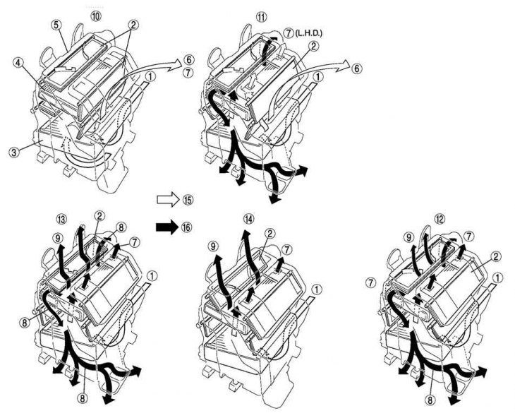
Fig. 8.80. Operation of the blower control flap: 1 – air flow; 2 – blower mode control flap; 3 – evaporator; 4 – heater radiator; 5 – air conditioning system unit; 6 – to the central channel; 7 – to the side channel; 8 – to the front and rear heating channels; 9 – to the heating system deflector and side channel; 10 – VENT; 11 – BI-LEVEL; 12 – HEAT; 13 – HEAT/DEF; 14 – DFROSTER; 15 – cold air; 16 – warm air
The blower mode control flap can be set to one of the following positions: VENT, BI-LEVEL, HEAT, HEAT/DEF or DEFROSTER, depending on the position of the blower mode regulator.
As a result, the air distribution mode changes.