


Car engine repair Mazda 6 (GG)

L8 and LF Engines — General Information
The Mazda 6 cars use 4-cylinder engines as a power plant, in which the cylinders are located in one row. The engine is covered from below by a sump, forming a crankcase,...
The Mazda 6 cars use 4-cylinder engines as a power plant, in which the cylinders are located in one row. The engine is covered from below by a sump, forming a crankcase,...
Checking the content of CO/CH in exhaust gases
The purpose of this test is to confirm that the CO/CH content in engine exhaust gases complies with the legal requirements for the toxicity of exhaust gases from vehicle...
The purpose of this test is to confirm that the CO/CH content in engine exhaust gases complies with the legal requirements for the toxicity of exhaust gases from vehicle...

Measuring compression in engine cylinders
Note: It is recommended to measure the compression in engine cylinders in the following cases: decreased engine power, increased engine oil consumption, increased fuel...
Note: It is recommended to measure the compression in engine cylinders in the following cases: decreased engine power, increased engine oil consumption, increased fuel...

Checking the accessory drive belt
Fig. 2.74. Checking the drive belt tension Check the position of the automatic drive belt tensioner indicator mark (Fig. 2.74). If the position of the mark is not...
Fig. 2.74. Checking the drive belt tension Check the position of the automatic drive belt tensioner indicator mark (Fig. 2.74). If the position of the mark is not...

Replacing the drive belt
Remove the right mudguard. Fig. 2.75. Loosening the drive belt tension Turn the center of the tensioner pulley clockwise to loosen the drive belt tension (Fig. 2.75)....
Remove the right mudguard. Fig. 2.75. Loosening the drive belt tension Turn the center of the tensioner pulley clockwise to loosen the drive belt tension (Fig. 2.75)....

Checking the automatic drive belt tensioner
Remove the drive belt. Fig. 2.76. Checking the automatic drive belt tensioner: 1 – Automatic drive belt tensioner Check the smooth movement of the automatic drive belt...
Remove the drive belt. Fig. 2.76. Checking the automatic drive belt tensioner: 1 – Automatic drive belt tensioner Check the smooth movement of the automatic drive belt...

Checking thermal clearances in the valve drive mechanism
Disconnect the negative battery cable. Remove the right wheel. Remove the right mudguard. Remove the spark plugs. Disconnect the high voltage wire. Disconnect the oil...
Disconnect the negative battery cable. Remove the right wheel. Remove the right mudguard. Remove the spark plugs. Disconnect the high voltage wire. Disconnect the oil...

Adjusting thermal clearances in the valve drive mechanism
Disconnect the negative battery cable. Remove the right wheel. Remove the right mudguard. Remove the spark plugs. Disconnect the high voltage wire. Disconnect the oil...
Disconnect the negative battery cable. Remove the right wheel. Remove the right mudguard. Remove the spark plugs. Disconnect the high voltage wire. Disconnect the oil...
General information and safety precautions when removing the power unit
If a decision has been made to remove the engine, then carry out preparatory measures before doing so. It is extremely important to determine the place where the work...
If a decision has been made to remove the engine, then carry out preparatory measures before doing so. It is extremely important to determine the place where the work...

Removal the sealant
Fig. 2.87. Removing old sealant After removing the mounting bolts and nuts, use a suitable sealant removal tool (Fig. 2.87). Caution! Be careful not to damage the...
Fig. 2.87. Removing old sealant After removing the mounting bolts and nuts, use a suitable sealant removal tool (Fig. 2.87). Caution! Be careful not to damage the...

Removal the power unit
Remove the battery. Remove the battery tray. Remove the radiator. Drain the oil. Remove the power steering oil pump with the oil filter without disconnecting the hose...
Remove the battery. Remove the battery tray. Remove the radiator. Drain the oil. Remove the power steering oil pump with the oil filter without disconnecting the hose...

Removal engine support #1
Fig. 2.90. Hanging the engine using a special device Suspend the engine using a special device (Fig. 2.90). Remove the tie bolt A from the side of the engine support...
Fig. 2.90. Hanging the engine using a special device Suspend the engine using a special device (Fig. 2.90). Remove the tie bolt A from the side of the engine support...

Removal Engine Mount Bracket #4 and Engine Mount #4
Fig. 2.92. Motor jack Secure the engine and gearbox in the block with the final drive using an engine jack and an additional device (Fig. 2.92). Fig. 2.89. Components of...
Fig. 2.92. Motor jack Secure the engine and gearbox in the block with the final drive using an engine jack and an additional device (Fig. 2.92). Fig. 2.89. Components of...

Installing Engine Mount Bracket #3
Fig. 2.95. Threaded (welded) stud of engine support bracket No.3: 1 - hairpin Tighten the threaded (welding) stud of engine support bracket No.3 to a tightening torque...
Fig. 2.95. Threaded (welded) stud of engine support bracket No.3: 1 - hairpin Tighten the threaded (welding) stud of engine support bracket No.3 to a tightening torque...

Installing Engine Mount Bracket #4 and Engine Mount #4
Fig. 2.97. Tightening order of the bolt and nut for fastening the bracket of engine support No.4 and engine support No.4 Tighten the bolt and nut securing the engine...
Fig. 2.97. Tightening order of the bolt and nut for fastening the bracket of engine support No.4 and engine support No.4 Tighten the bolt and nut securing the engine...

Installing Engine Support No. 1
Tighten engine mount bracket bolt A to a torque of 93.1–116.6 N·m. Tighten engine mount bracket bolt B to a torque of 93.1–116.6 N·m. Tighten the engine support bracket...
Tighten engine mount bracket bolt A to a torque of 93.1–116.6 N·m. Tighten engine mount bracket bolt B to a torque of 93.1–116.6 N·m. Tighten the engine support bracket...

Checking the actuator of variable valve timing (L3)
Attention! The actuator of variable valve timing is a precision unit and cannot be disassembled. Disconnect the negative battery cable. Remove the plug hole plate....
Attention! The actuator of variable valve timing is a precision unit and cannot be disassembled. Disconnect the negative battery cable. Remove the plug hole plate....

Removal and installation the variable valve timing actuator (L3)
Note: The camshaft sprocket of the variable valve timing actuator is integrated with the mechanism itself, so it is removed together with the unit. Remove the timing...
Note: The camshaft sprocket of the variable valve timing actuator is integrated with the mechanism itself, so it is removed together with the unit. Remove the timing...
Timing Chain — Preliminary Operations
Disconnect the negative battery cable. Remove the spark plugs. Remove the right wheel. Remove the right mudguard. Loosen the coolant pump pulley mounting bolt and remove...
Disconnect the negative battery cable. Remove the spark plugs. Remove the right wheel. Remove the right mudguard. Loosen the coolant pump pulley mounting bolt and remove...

Removal the crankshaft pulley mounting bolt
Remove the lower cylinder block plug. Fig. 2.103. Installation of a special device Install a special device (fig. 2.103). Turn the crankshaft clockwise to TDC of the...
Remove the lower cylinder block plug. Fig. 2.103. Installation of a special device Install a special device (fig. 2.103). Turn the crankshaft clockwise to TDC of the...

Removal the chain tensioner
Fig. 2.105. Installing a special device on the crankshaft: 1 – tensioner piston Using a thin screwdriver, pry the chain tensioner ratchet away from the ratchet rod (fig....
Fig. 2.105. Installing a special device on the crankshaft: 1 – tensioner piston Using a thin screwdriver, pry the chain tensioner ratchet away from the ratchet rod (fig....

Removal the timing chain
Fig. 2.106. Fixing the oil pump sprocket: 1 – special device Secure the oil pump sprocket with a special tool (fig. 2.106). After this, remove the sprocket and chain....
Fig. 2.106. Fixing the oil pump sprocket: 1 – special device Secure the oil pump sprocket with a special tool (fig. 2.106). After this, remove the sprocket and chain....

Installing the timing chain
Fig. 2.106. Fixing the oil pump sprocket: 1 – special device Install the oil pump sprocket and secure it with a special tool (see fig. 2.106). Fig. 2.86. Installing a...
Fig. 2.106. Fixing the oil pump sprocket: 1 – special device Install the oil pump sprocket and secure it with a special tool (see fig. 2.106). Fig. 2.86. Installing a...

Installing the front engine cover
Apply silicone sealant to the front engine cover in the areas shown in Figure 2.108. Fig. 2.108. Places where sealant is applied to the front engine cover Note: Install...
Apply silicone sealant to the front engine cover in the areas shown in Figure 2.108. Fig. 2.108. Places where sealant is applied to the front engine cover Note: Install...

Installing the front crankshaft oil seal
Apply clean engine oil to the seal. Lightly press the seal in by hand. Fig. 2.110. Pressing in the front oil seal: 1- special device Press in the seal using a special...
Apply clean engine oil to the seal. Lightly press the seal in by hand. Fig. 2.110. Pressing in the front oil seal: 1- special device Press in the seal using a special...

Installing Engine Rubber Mount #3 and Engine Mount Bracket #3
Fig. 2.95. Threaded (welded) stud of engine support bracket No.3: 1 - hairpin Tighten the threaded stud of engine support bracket No.3 to a tightening torque of 7–13 N·m...
Fig. 2.95. Threaded (welded) stud of engine support bracket No.3: 1 - hairpin Tighten the threaded stud of engine support bracket No.3 to a tightening torque of 7–13 N·m...

Installing the crankshaft pulley mounting bolt
Fig. 2.86. Installing a special device on the camshaft Install the special tool on the camshaft (see fig. 2.86). Fig. 2.113. Crankshaft pulley lock bolt: 1 – bolt...
Fig. 2.86. Installing a special device on the camshaft Install the special tool on the camshaft (see fig. 2.86). Fig. 2.113. Crankshaft pulley lock bolt: 1 – bolt...

Installing the cylinder head cover
Apply silicone sealant to the mating surfaces of the cylinder block in the areas shown by the arrows (Fig. 2.114). The diameter of the application point is 4.0–6.0 mm....
Apply silicone sealant to the mating surfaces of the cylinder block in the areas shown by the arrows (Fig. 2.114). The diameter of the application point is 4.0–6.0 mm....

Removal and installation the oil control valve (OCV) (L3)
Disconnect the negative battery cable. Remove the plug hole plate. Remove the high voltage wire. Disconnect the oil control valve (OCV) connector. Measure the resistance...
Disconnect the negative battery cable. Remove the plug hole plate. Remove the high voltage wire. Disconnect the oil control valve (OCV) connector. Measure the resistance...

Checking the Oil Control Valve (OCV) (L3)
Disconnect the negative battery cable. Disconnect the oil control valve connector. Fig. 2.103. Installation of a special device Measure the resistance between terminals...
Disconnect the negative battery cable. Disconnect the oil control valve connector. Fig. 2.103. Installation of a special device Measure the resistance between terminals...

Checking the operation of the spool valve (OCV) (L3)
Disconnect the negative battery cable. Remove the oil control valve. Fig. 2.118. Primary check of the position of the spool valve of the control oil valve: 1 – spool...
Disconnect the negative battery cable. Remove the oil control valve. Fig. 2.118. Primary check of the position of the spool valve of the control oil valve: 1 – spool...

Disassembling the cylinder head
Fig. 2.120. Components of the first stage of disassembling the cylinder head: 1 – camshaft sprocket mounting bolts; 2 – camshaft sprockets; 3 – Oil control valve...
Fig. 2.120. Components of the first stage of disassembling the cylinder head: 1 – camshaft sprocket mounting bolts; 2 – camshaft sprockets; 3 – Oil control valve...

Disassembling the cylinder block
Remove the cylinder head. Remove the oil pan. Remove the oil filter. Remove the oil cooler. Remove the knock sensor. Remove the oil separator. Remove the thermostat....
Remove the cylinder head. Remove the oil pan. Remove the oil filter. Remove the oil cooler. Remove the knock sensor. Remove the oil separator. Remove the thermostat....

Checking the cylinder head
Fig. 2.136. Using dye when checking the cylinder block Perform a color contrast inspection of the cylinder head surface. Using a penetrating dye, check for cracks in the...
Fig. 2.136. Using dye when checking the cylinder block Perform a color contrast inspection of the cylinder head surface. Using a penetrating dye, check for cracks in the...

Checking the valve guide bushing
Fig. 2.138. Measuring the thickness of the valve head Measure the thickness of each valve head (fig. 2.138). If the thickness is not within the standard, replace the...
Fig. 2.138. Measuring the thickness of the valve head Measure the thickness of each valve head (fig. 2.138). If the thickness is not within the standard, replace the...

Measuring valve length
Fig. 2.139. Valve length Measure the length of each valve (fig. 2.139). If the length is not within specification, replace the valve. Standard length L: Intake:...
Fig. 2.139. Valve length Measure the length of each valve (fig. 2.139). If the length is not within specification, replace the valve. Standard length L: Intake:...

Measuring the valve stem diameter
Fig. 2.140. Measuring the rod diameter Measure the stem diameter of each valve with a micrometer in the X and Y directions at three points (A, B, and C) as shown in...
Fig. 2.140. Measuring the rod diameter Measure the stem diameter of each valve with a micrometer in the X and Y directions at three points (A, B, and C) as shown in...

Measuring the inside diameter of the valve guide bushing
Fig. 2.141. Measuring the inner diameter of the valve guide bushing Measure the inside diameter of each valve guide in the X and Y directions at three points (A, B, and...
Fig. 2.141. Measuring the inner diameter of the valve guide bushing Measure the inside diameter of each valve guide in the X and Y directions at three points (A, B, and...

Measuring the valve guide protrusion height
Fig. 2.143. Measured height: 1 – valve guide bushing; 2 – cylinder head Measure the protrusion height (dimension A) of each valve guide excluding the lower valve spring...
Fig. 2.143. Measured height: 1 – valve guide bushing; 2 – cylinder head Measure the protrusion height (dimension A) of each valve guide excluding the lower valve spring...

Replacing the valve guide bushing
Fig. 2.144. Removing the valve guide bushing: 1 – valve guide bushing Remove the valve guide bushing from the combustion chamber side using a special tool (fig. 2.144)....
Fig. 2.144. Removing the valve guide bushing: 1 – valve guide bushing Remove the valve guide bushing from the combustion chamber side using a special tool (fig. 2.144)....

Pressing in the valve guide bushing
Fig. 2.146. Pressing in the valve guide bushing: 1 – valve guide bushing Press the valve guide bushing from the side opposite the camshaft until the special tool stops...
Fig. 2.146. Pressing in the valve guide bushing: 1 – valve guide bushing Press the valve guide bushing from the side opposite the camshaft until the special tool stops...

Checking and repairing the valve seat
Fig. 2.147. Measuring the valve seat width Measure the width of the valve seat contact surface. If necessary, machine the valve seat or plate using the appropriate...
Fig. 2.147. Measuring the valve seat width Measure the width of the valve seat contact surface. If necessary, machine the valve seat or plate using the appropriate...

Checking the valve spring
Fig. 2.150. Checking the valve spring height Apply compressive force to the spring and check the height of the spring (fig. 2.150). If the height is not within...
Fig. 2.150. Checking the valve spring height Apply compressive force to the spring and check the height of the spring (fig. 2.150). If the height is not within...

Checking the camshaft
Install camshaft journals No.1 and No.5 on the prisms. Fig. 2.152. Measuring camshaft runout Measure the camshaft runout (fig. 2.152). If the runout is not within...
Install camshaft journals No.1 and No.5 on the prisms. Fig. 2.152. Measuring camshaft runout Measure the camshaft runout (fig. 2.152). If the runout is not within...

Measuring the diameter of the camshaft journal
Fig. 2.154. Measuring the camshaft journal diameter Measure the journal diameters of the shaft in the X and Y directions at two points (A and B) as shown in Figure...
Fig. 2.154. Measuring the camshaft journal diameter Measure the journal diameters of the shaft in the X and Y directions at two points (A and B) as shown in Figure...

Measuring the radial clearance of the camshaft journal
Remove the valve lifter. Fig. 2.155. Installation of calibrated plastic wire Place pieces of calibrated plastic wire on top of the camshaft journals, aligning them along...
Remove the valve lifter. Fig. 2.155. Installation of calibrated plastic wire Place pieces of calibrated plastic wire on top of the camshaft journals, aligning them along...

Measuring the axial clearance of the camshaft journal
Install the camshaft bearing cap. Fig. 2.156. Measuring the axial clearance of the camshaft Measure the axial clearance of the camshaft (fig. 2.156). If the clearance is...
Install the camshaft bearing cap. Fig. 2.156. Measuring the axial clearance of the camshaft Measure the axial clearance of the camshaft (fig. 2.156). If the clearance is...

Checking the valve tappet
Fig. 2.157. Measuring the internal diameter of the valve tappet hole Measure the valve tappet bore inner diameter in X and Y directions at two points (A and B) (fig....
Fig. 2.157. Measuring the internal diameter of the valve tappet hole Measure the valve tappet bore inner diameter in X and Y directions at two points (A and B) (fig....

Checking the cylinder block
Fig. 2.159. Measuring the degree of warpage of the cylinder block surface Measure the degree of warpage of the cylinder block surface in six directions as shown in...
Fig. 2.159. Measuring the degree of warpage of the cylinder block surface Measure the degree of warpage of the cylinder block surface in six directions as shown in...
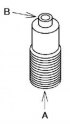
Checking the oil spray nozzle valve
Fig. 2.161. Oil spray nozzle valve testing diagram Apply compressed air to the oil spray nozzle valve A and make sure that air passes through valve B (fig. 2.161). If...
Fig. 2.161. Oil spray nozzle valve testing diagram Apply compressed air to the oil spray nozzle valve A and make sure that air passes through valve B (fig. 2.161). If...

Checking the crankshaft
Install the main bearing cap. Measure the crankshaft end clearance. If the clearance is not within specification, replace the thrust bearing or crankshaft to obtain the...
Install the main bearing cap. Measure the crankshaft end clearance. If the clearance is not within specification, replace the thrust bearing or crankshaft to obtain the...

Measuring the crankshaft runout value
Remove the main bearing cap. Measure the crankshaft runout. If the crankshaft runout value exceeds the maximum, replace the crankshaft. Fig. 2.166. Measuring the...
Remove the main bearing cap. Measure the crankshaft runout. If the crankshaft runout value exceeds the maximum, replace the crankshaft. Fig. 2.166. Measuring the...

Measuring the diameters of the crankshaft journals
Fig. 2.167. Measuring the diameters of the crankshaft journals Measure the journal diameters of the shaft in the X and Y directions at two points (A and B) as shown in...
Fig. 2.167. Measuring the diameters of the crankshaft journals Measure the journal diameters of the shaft in the X and Y directions at two points (A and B) as shown in...

Measuring the radial clearance in the crankshaft main bearings
Install the main bearing cap and crankshaft. Place pieces of calibrated plastic wire on top of the shaft journals, aligning them along the axis. Install the main bearing...
Install the main bearing cap and crankshaft. Place pieces of calibrated plastic wire on top of the shaft journals, aligning them along the axis. Install the main bearing...

Checking the connecting rod side clearance
Install the connecting rod cover. Fig. 2.169. Measuring the lateral clearance of the lower connecting rod head Measure the side clearance of the connecting rod lower...
Install the connecting rod cover. Fig. 2.169. Measuring the lateral clearance of the lower connecting rod head Measure the side clearance of the connecting rod lower...

Measuring the radial clearance of the connecting rod
Remove the connecting rod cover. Fig. 2.170. Installation location of calibrated plastic wire Place pieces of calibrated plastic wire on top of the camshaft journals,...
Remove the connecting rod cover. Fig. 2.170. Installation location of calibrated plastic wire Place pieces of calibrated plastic wire on top of the camshaft journals,...

Checking the cylinder head bolts
Fig. 2.171. Measuring the length of a bolt Measure the length of each bolt (fig. 2.171). Replace all bolts that exceed the maximum length. Length L
Fig. 2.171. Measuring the length of a bolt Measure the length of each bolt (fig. 2.171). Replace all bolts that exceed the maximum length. Length L

Installing main bearing caps
Fig. 2.172. The order of tightening the bolts securing the main bearing caps Install the main bearing caps and tighten the mounting bolts in the order shown in Figure...
Fig. 2.172. The order of tightening the bolts securing the main bearing caps Install the main bearing caps and tighten the mounting bolts in the order shown in Figure...

Installing piston rings
Fig. 2.173. Oil scraper ring installation diagram Install two oil scraper ring segments and an expander (fig. 2.173). Make sure the second ring is installed with the...
Fig. 2.173. Oil scraper ring installation diagram Install two oil scraper ring segments and an expander (fig. 2.173). Make sure the second ring is installed with the...

Piston assembly
Fig. 2.174. Piston ring lock arrangement diagram: 1 - top ring; 2 – upper oil scraper ring; 3 – lower oil scraper ring; 4 – oil scraper ring expander and second ring...
Fig. 2.174. Piston ring lock arrangement diagram: 1 - top ring; 2 – upper oil scraper ring; 3 – lower oil scraper ring; 4 – oil scraper ring expander and second ring...

Installing the connecting rod bearing and cover
Fig. 2.176. Installing the connecting rod bearing Install the connecting rod bearings into the connecting rod head and cap as shown in Figure 2.176. Caution! When...
Fig. 2.176. Installing the connecting rod bearing Install the connecting rod bearings into the connecting rod head and cap as shown in Figure 2.176. Caution! When...

Assembly of the balancing unit (L3 with variable valve timing mechanism
Make sure that the balancing unit gear is not damaged and that the shaft rotates smoothly. Attention! The balancing unit cannot be disassembled, as it has a high...
Make sure that the balancing unit gear is not damaged and that the shaft rotates smoothly. Attention! The balancing unit cannot be disassembled, as it has a high...

Installing the drive disk (with automatic transmission), flywheel (with manual transmission)
Hold the crankshaft from turning using a special device. Fig. 2.180. The order of tightening the flywheel or drive disk mounting bolts Tighten the mounting bolts in the...
Hold the crankshaft from turning using a special device. Fig. 2.180. The order of tightening the flywheel or drive disk mounting bolts Tighten the mounting bolts in the...
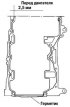
Installing the oil pan
Fig. 2.181. Places of application of sealant on the mating surface of the oil pan Apply a continuous bead of silicone sealant to the mating surface of the oil pan as...
Fig. 2.181. Places of application of sealant on the mating surface of the oil pan Apply a continuous bead of silicone sealant to the mating surface of the oil pan as...

Cylinder head assembly
Install the cooling system outlet pipe housing. Install the recirculation tube. Installing the oil seal Press the valve stem seal onto the valve guide by hand. Fig....
Install the cooling system outlet pipe housing. Install the recirculation tube. Installing the oil seal Press the valve stem seal onto the valve guide by hand. Fig....

Assembly of the timing mechanism drive
Install the crankshaft sprocket. Install the oil pump chain. Fig. 2.189. Fixing the oil pump chain with a special device Secure the oil pump sprocket with a special tool...
Install the crankshaft sprocket. Install the oil pump chain. Fig. 2.189. Fixing the oil pump chain with a special device Secure the oil pump sprocket with a special tool...
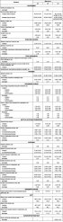
Technical data of the mechanical part of engines of models L8, LF, L3
Table 2.24. Technical data of the mechanical part of engines of models L8, LF, L3
Table 2.24. Technical data of the mechanical part of engines of models L8, LF, L3
This section is available on: russian, bulgarian, belarusian, ukrainian, serbian, croatian, romanian, polish, slovak, hungarian
More sections on repairs of other Mazda models
• Power unit: Engine repair Mazda Capella 4 (1987-1992)
• Power unit: Engine repair (gasoline) Mazda3 BK (2003-2009)
• Power unit: Engine repair Mazda Capella 4 (1987-1992)
• Power unit: Engine repair (gasoline) Mazda3 BK (2003-2009)
Link in different formats to this section
TEXTHTMLBB Code
- User manual
- Vehicle description
- Keys, locks and alarms
- Controls and instruments
- Air conditioning and heater
- Seat adjustment
- Security systems
- Driving and operation
- Faults en route
- Maintenance
- Power unit
- Engine device
- Engine repair
- Lubrication system
- Cooling system
- Fuel system
- Exhaust system
- Electrical equipment of engines
- Control system
- Transmission
- Clutch
- Mechanical gearbox
- Automatic gearbox
- Drive shafts and hubs
- Chassis
- Suspension and wheels
- Steering
- Brake system
- Body
- Exterior (external elements)
- Interior (internal elements)
- Doors and windows
- Air conditioning and heater
- Electrical equipment
- Equipment and devices
- Power devices
- Lighting system
- Windshield wipers and washers