


Remove the right wheel.
Remove the right mudguard.
Remove the spark plugs.
Disconnect the high voltage wire.
Disconnect the oil control valve (OCV) connector.
Remove the ventilation hose.
Remove the cylinder head cover. Make sure the engine is cold.
Remove the drive belt.
Remove the right joint shaft from the intermediate propeller shaft.
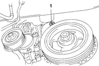
Fig. 2.78. Lower plug of the front engine cover: 1 – plug
[Original material on the website: MAZBOOK]
Remove the lower plug of the front engine cover (Fig. 2.78).
Remove the top plug of the front engine cover.
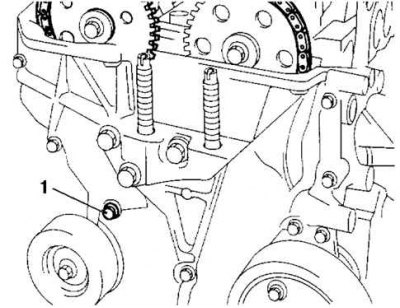
Fig. 2.79. Lower plug of the cylinder block: 1 – plug
Remove the lower plug of the cylinder block (Fig. 2.79).
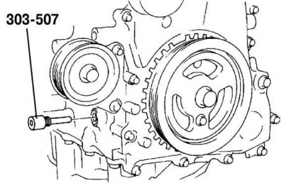
Fig. 2.80. Installation of a special device
Install the special device (Fig. 2.80).
Turn the crankshaft clockwise to TDC of the piston of cylinder No.1.
Loosen the timing chain.
a) Using a suitable screwdriver or similar tool, release the chain tensioner ratchet.
b) Turn the exhaust camshaft clockwise using the appropriate wrench (hexagon) and loosen the timing chain.
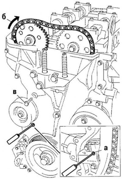
Fig. 2.81. Fixing the chain guide in the loose position
c) By placing the appropriate bolt (M6 1.0 length 25-35 mm) in the hole of the upper plug of the front engine cover, fix the chain guide in the loose position (Fig. 2.81).
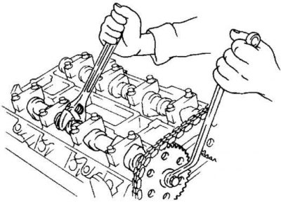
Fig. 2.82. Fixing the exhaust valve drive camshafts
Secure the exhaust camshaft using the appropriate wrench (hexagon) (Fig. 2.82).
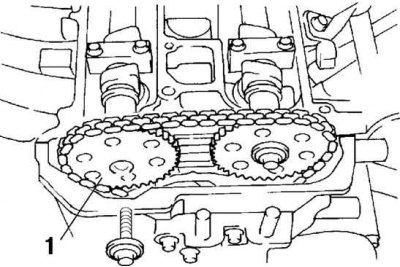
Fig. 2.83. Lower plug of the cylinder block: 1 – intake camshaft sprocket
Remove the exhaust camshaft drive sprocket (Fig. 2.83).
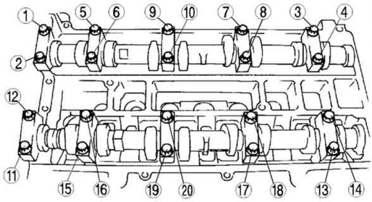
Fig. 2.84. The order of loosening the camshaft bolts
Loosen the camshaft bolts in several steps in the order shown (Fig. 2.84).
Note: The cylinder head and camshaft bearing caps are numbered to facilitate their reinstallation in their original position during assembly. After removal, keep the caps together with the cylinder head from which they were removed. Do not mix the caps.
Remove the camshaft.
Remove the valve lifter.
Select the appropriate adjusting shim using the following diagram and notes made during the initial inspection as a guide:
new adjusting shim = removed shim + measured valve clearance – standard valve clearance.
- inlet - 0.25 mm;
- release - 0.30 mm.
Standard (on a cold engine):
- inlet - 0.22–0.28 mm (0.25±0.03 mm);
- release - 0.27–0.33 mm (0.30±0.03 mm).
Install the camshaft, the piston of cylinder No.1 should be in the TDC position.
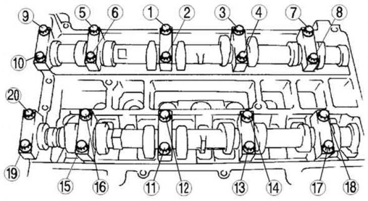
Fig. 2.85. Camshaft bolt tightening sequence
Tighten the camshaft bolt in two steps (Fig. 2.85):
- torque 5.0–9.0 Nm;
- torque of 14.0–17.0 N·m.
Install the exhaust camshaft sprocket (see fig. 2.83).
Note: Do not tighten the camshaft sprocket bolt. First check the valve opening or closing timing, then tighten the bolt.
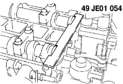
Fig. 2.86. Installing a special device on the camshaft
Install a special device on the camshaft (Fig. 2.86).
Remove the bolt (M6x1.0, length 25-35 mm) from the front engine cover to tighten the timing chain.
Turn the crankshaft clockwise to TDC of the piston of cylinder No.1.
Hold the exhaust camshaft using a suitable wrench (hexagon) (see fig. 2.82).
Tighten the exhaust camshaft sprocket bolt to a torque of 69–75 N·m.
Remove the special tool from the camshaft.
Remove the special tool from the hole in the lower block plug.
Turn the crankshaft clockwise two revolutions to the TDC position. If the TDC position is not reached, loosen the crankshaft pulley bolt and perform all operations, starting with installing the special device (see fig. 2.80).
Apply silicone sealant to the top plug of the front engine cover.
Install the upper plug of the front engine cover, tightening it to a tightening torque of 10 N·m.
Install the lower cylinder block plug, tightening it to a tightening torque of 18–22 N·m.
Install a new lower plug of the front engine cover, tightening it to a torque of 12 N·m.
Install the right intermediate drive shaft and the joint shaft.
Install the drive belt.
Install the cylinder head cover.
Connect the ventilation hose.
Connect the oil control valve (OCV) connector.
Connect the high voltage wire.
Screw in the spark plugs.
Install the right mudguard.
Install the right wheel.