
2. Remove the following parts so that the crankshaft can be rotated.
A) Remove the accessory drive belt (see chapter "Maintenance and general inspection and adjustment procedures").
b) Remove the cooling fan (see chapter "Cooling system").
V) Remove the coolant pump pulley.
3. Remove nozzles (see chapter "fuel injection system").
4. Remove the cylinder head cover.
5. Turn the engine crankshaft clockwise so that the piston in the first cylinder is at TDC on the compression stroke.
6. Measure the clearances in the valve drive, marked in the figure with the letter "A". Record the measured values on paper.
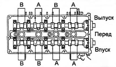
7. Rotate the crankshaft clockwise 360°so that the fourth cylinder piston is at TDC on the compression stroke.
8. Measure the clearances in the valve drive, marked in the figure with the letter "IN". Record the measured values on paper.
Rated clearance (on a cold engine):
- intake valves - 0.10-0.16 mm
- exhaust valves - 0.17-0.20 mm
If the clearances in the valve drive do not correspond to the specified ones, adjust them.
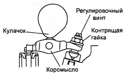
A) Install the camshaft (turning the crankshaft clockwise) to a position in which the camshaft cam will fully press on the valve rocker, the clearance of which must be adjusted. Loosen the lock nut and adjusting screw.
Caution: Loosen the lock nut and adjusting screw only when the camshaft lobe is fully pressed on the rocker arm as shown in the illustration. Otherwise, when the crankshaft rotates, the bearing part of the rocker arm in contact with the valve may be damaged.
b) Turn the crankshaft to set the piston in the corresponding cylinder to TDC on the compression stroke.
Note: to adjust the clearances in the valves indicated in the figure by letters "A" it is necessary to install the piston in cylinder No. 1 at TDC on the compression stroke, and to adjust the clearances in the valves indicated in the figure with letters "IN", it is necessary to set the piston in cylinder No. 4 to TDC on the compression stroke (see picture in paragraph "6").
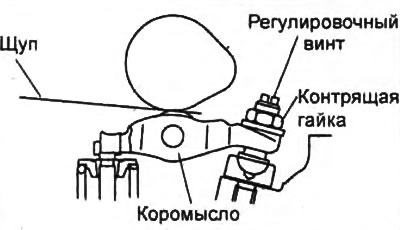
V) By turning the adjusting screw, set the required clearance in the valve actuator of the corresponding cylinder.
G) Tighten the lock nut and recheck the thermal clearance in the valve actuator.
- Tightening torque - 20-24 Nm
d) Rotate the crankshaft 360°and check the valve clearance. Repeat the adjustment if necessary.
9. Install the cylinder head cover (see section "cylinder head").
10. Next, the parts are installed in the reverse order of removal.
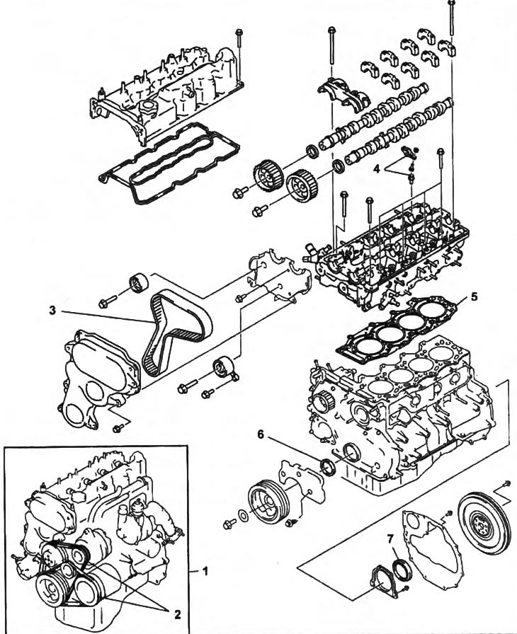
WL engine.
1 - engine assembly,
2 - drive belts for attachments,
3 - timing belt,
4 - rocker,
5 - cylinder head gasket,
6 - front crankshaft oil seal,
7 - crankshaft rear oil seal.