
Intake Air Flow Variation System (VSC)
System of change of intensity of a stream of air on inlet VSC.
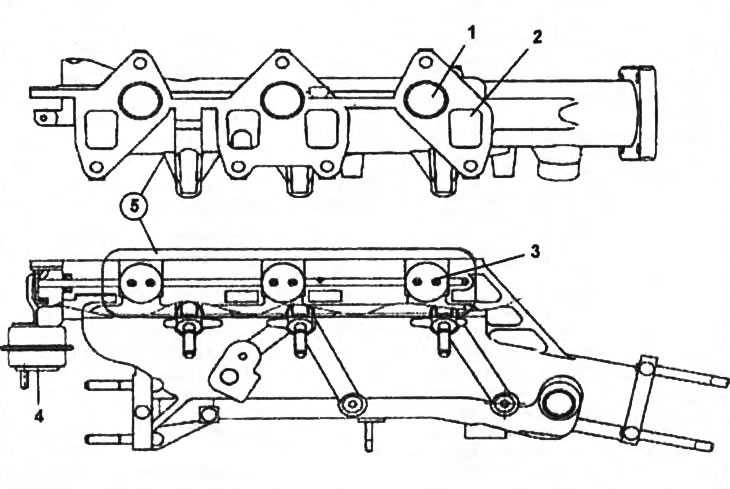
1 - secondary inlet port,
2 - primary inlet port,
3 - damper VSC,
4 - pneumatic drive dampers VSC,
5 - intake manifold.
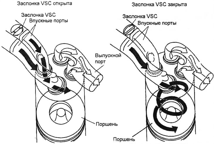
The operation of the system for changing the intensity of the air flow at the intake of the VSC.
The system consists of an electro-pneumatic valve, an actuator and four dampers installed in the intake manifold and blocking one of the two intake ports of each engine cylinder. The system serves to reduce the toxicity of exhaust gases at low crankshaft speeds. At a low speed, at the signal of the engine control unit, the electro-pneumatic valve opens the vacuum channel, as a result of which vacuum is applied to the VSC system drive. Under the action of vacuum, the drive closes one of the inlet ports of each cylinder with the help of dampers, as a result of which air is supplied to the open inlet port with greater intensity and a swirl occurs in the cylinder, which contributes to better fuel evaporation, distribution of the air-fuel mixture over the volume of the combustion chamber, as well as helps to reduce smoke.
Turbocharger with variable vane geometry
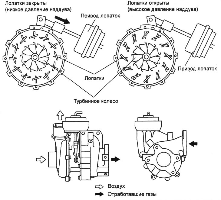
The operation of the turbocharger with variable geometry guide vanes.
The new generation WL engine is equipped with a turbocharger with a geometry change system (changing the position of the blades placed in the nozzle apparatus) VGT (Variable Geometry Turbocharger).
The main advantages of a variable geometry turbocharger are as follows.
When running at low engine speeds for a conventional turbocharger with an exhaust gas bypass valve (installed welt on WL-T engines) there is a phenomenon called "turbo pit", caused by a decrease in flow (quantity) and pressure (and with it the speed) exhaust gases. In other words, the flow of exhaust gases is insufficient to bring the turbine, connected directly to the compressor, to the operating speed at which the turbocharger is effective. Consequently, the boost pressure drops, and with it, both the filling of the cylinders and the engine torque decrease. The use of a variable geometry turbocharger minimizes the phenomenon "turbo pits" by changing the flow area in the turbine nozzle apparatus. With a decrease in the flow area in the turbine nozzle apparatus, the pressure of the exhaust gases in front of it increases, which is then converted after passing through the nozzle apparatus into the speed of the flow incident on the turbine wheel. The speed of the turbine wheel increases, the speed of the compressor wheel increases, and hence the boost pressure.
The turbocharger uses the energy of the exhaust gases to further compress the intake air and deliver it to the cylinders with higher pressure and density, resulting in more power, lower fuel consumption and improved engine performance.
The change in boost pressure is carried out by changing the position of the guide vanes mounted on the turbine housing. The position of the guide vanes is controlled by the engine control unit using the boost pressure control solenoid valve.
At the signal of the engine control unit, the solenoid valve opens, connecting the vacuum channel between the vacuum pump and the air drive of the turbocharger guide vanes, as a result of which the drive rod connected to the lever of the vane position control mechanism begins to retract into the drive, thereby adjusting the opening angle of the guide vanes and pressure boost.
When idle, the turbocharger blades are as open as possible and direct more exhaust gases to the turbine wheel, causing the turbine wheel to rotate faster under the energy of a small exhaust gas flow. Through the shaft, rotation is transmitted to the compressor wheel, which pumps more air into the intake tract, this helps to increase the boost pressure and fill the cylinders at low crankshaft speeds.
With an increase in the crankshaft speed and an increase in the flow of exhaust gases, the engine control unit begins to regulate the opening angle of the guide vanes by applying vacuum to their drive through the solenoid valve. Under the action of the drive rod, the blades begin to close until they are completely closed. The flow of exhaust gases directed to the turbine wheel is reduced and the boost pressure is reduced. In this mode, the turbine wheel rotates at a lower speed with a higher exhaust gas flow.
This is necessary to prevent damage to the turbocharger as a result of overloading (exceeding the maximum speed) and engine damage.
After passing through the compressor wheel and being compressed, the air heats up and its density decreases. To cool the charge air and increase its density, an aluminum alloy cooler is installed after the turbocharger. This is necessary to improve the filling of the cylinders.