Contents: Note on removing the oil pan ⇓ Note on removing the crankshaft…⇓ Note on removing the fuel injection…⇓ Note on removing the fuel injection…⇓ Note on removing the fuel injection…⇓ Note on flywheel removal ⇓ Note on removing the rear crankshaft…⇓ Note on installing the oil pump cover ⇓ Note on installing the crankshaft…⇓ Flywheel Installation Note ⇓ Note on installing the fuel…⇓ Note on installation of fuel…⇓ Note on installing the fuel…⇓ Note on installing the crankshaft…⇓
The procedures for disassembling, checking, cleaning, repairing and disassembling the cylinder block parts are discussed in Chapter "Engine - General Repair Procedures".
Note on removing the oil pan
See chapter "Lubrication system" and the figure "Preliminary disassembly and assembly of the cylinder block (stage 1)".
Note on removing the crankshaft pulley and fuel injection pump pulley
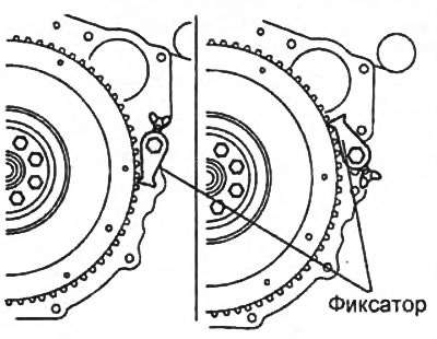
Using a locking device, secure the flywheel and remove the pulley.
Note on removing the fuel injection pump drive gear cover
1. Using a special separator, cut off the sealant and remove the cover of the fuel injection pump drive gear mechanism.
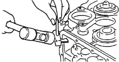
2. Remove the fuel injection pump drive gear cover seal using a slotted screwdriver wrapped in a rag.
Note on removing the fuel injection pump gear
1. Turn the engine crankshaft clockwise so that the piston in the first cylinder is in the TDC position on the compression stroke.
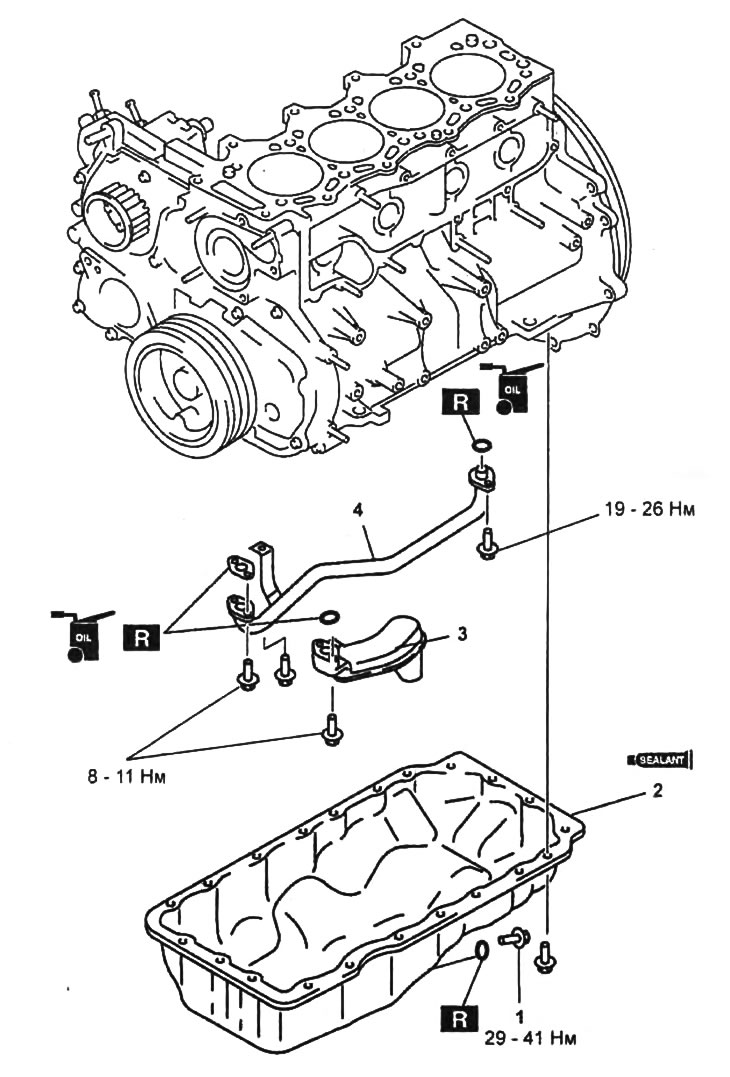
Preliminary disassembly and assembly of the cylinder block (stage 1).
1 - oil pan drain bolt,
2 - oil pan,
3 - oil receiver,
4 - oil pipe.
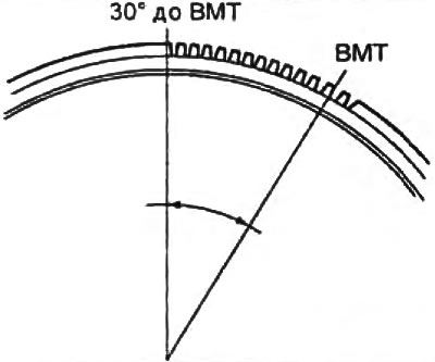
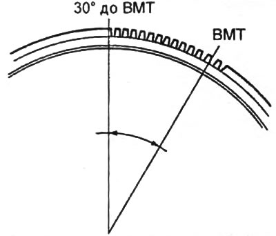
2. Turn the flywheel and set the piston in the first cylinder to 30° before TDC (13 teeth).
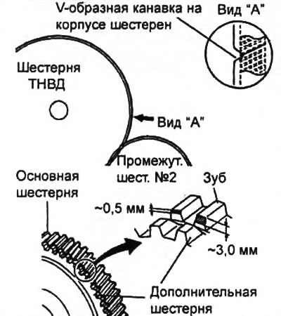
3. Make sure that the V-groove on the gear housing is aligned with the tooth of the injection pump gear, which has a large bevel cut.
Note: If a tooth with a large cut is difficult to locate, move the injection pump gear back and forth on the key and locate the tooth.
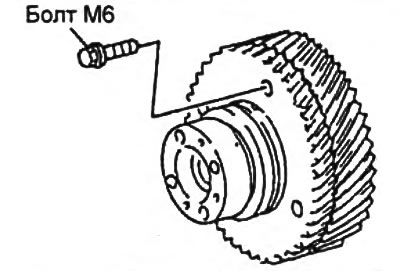
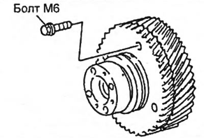
4. Fix the additional gear of the fuel injection pump to the main gear by screwing a bolt No.6X1.0 with a thread length of 16 mm into the gears.
Caution: When removing the fuel injection pump gear, make sure that the additional gear is securely fixed with a bolt to the main gear, otherwise the additional gear may rotate under the force of the spring, which may cause injury, and will also lead to the displacement of the additional gear relative to the desired position, as a result of which the fuel injection pump gear will not correctly engage with the intermediate gear No.2.
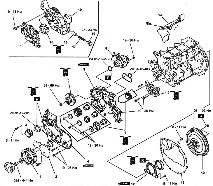
Preliminary disassembly and assembly of the cylinder block (stage 2).
1 - crankshaft pulley,
2, 13 - sealing cover,
3 - fuel injection pump toothed pulley,
4 - front cover of the gear mechanism,
5 - oil pump housing assembly,
6 - fuel injection pump drive gear,
7 - elements of the gear mechanism of the fuel injection pump drive,
8 - Fuel injection pump,
9 - gear mechanism housing,
10 - flywheel,
11 - back plate,
12 - crankshaft rear oil seal holder,
14 - oil pump cover,
15 - driven rotor,
16 - plug,
17 - spring,
18 - pressure reducing valve,
19 - oil pump housing.
5. Unscrew the fuel injection pump gear mounting nut, securing the flywheel from turning with a special tool.
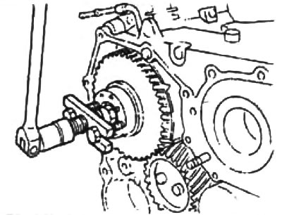
6. Using a puller, remove the fuel injection pump gear.
Note on removing the fuel injection pump drive gear housing
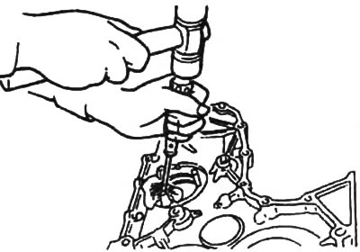
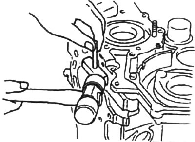
Using a hammer and a special separator, cut off the sealant and remove the fuel injection pump drive mechanism housing.
Note on flywheel removal
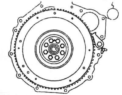
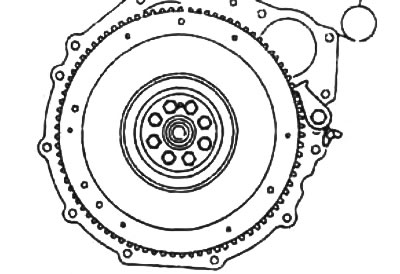
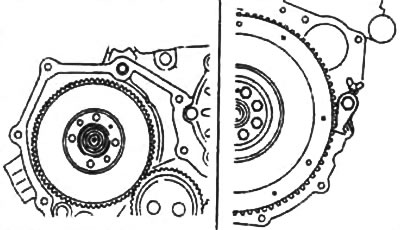
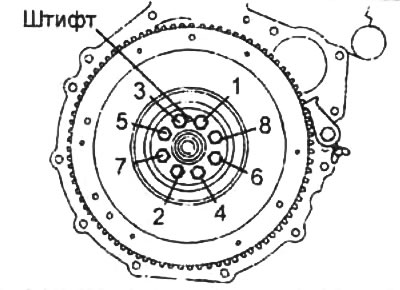
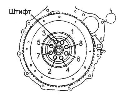
Using a locking device, secure the flywheel and remove it by unscrewing the mounting bolts in the sequence shown in the figure.
Note on removing the rear crankshaft oil seal
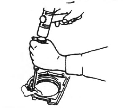
Using a screwdriver wrapped in a cloth, remove the seal.
Note on installing the oil pump cover
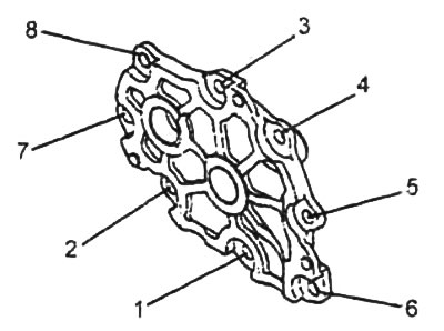
Tighten the oil pump cover mounting bolts in several passes in the sequence shown in the figure.
- Tightening torque - 9-13 Nm
Note on installing the crankshaft rear oil seal holder
1. Apply a layer of engine oil to the lip of the oil seal.
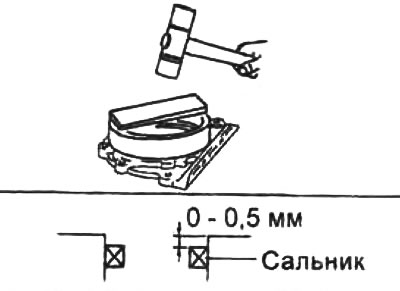
2. Using a drift of suitable diameter and a hammer, press the oil seal into the rear oil seal holder.
3. Apply silicone sealant to the contact surface of the crankshaft rear oil seal holder and install the holder together with the oil seal on the cylinder block.
- Sealant thickness: 2-3 mm
Note: The parts must be installed within the time specified in the sealant application instructions. Otherwise, the sealant must be removed and reapplied.
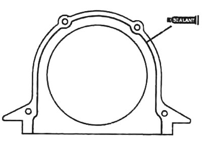
4. Apply a layer of sealant to the contact surface of the rear oil seal holder as shown in the figure.
- Sealant thickness: 2-3 mm
Note: The parts must be installed within the time specified in the sealant application instructions. Otherwise, the sealant must be removed and reapplied.
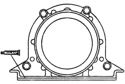
5. Install the back plate.
Flywheel Installation Note
1. Fix the crankshaft with a locking device.
2. Tighten the flywheel mounting bolts in the sequence shown in the figure.
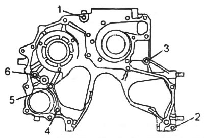
Note on installing the fuel injection pump drive gear housing
1. Install a new sealing ring into the fuel injection pump drive mechanism housing.
2 Apply silicone sealant to the surface of the fuel injection pump drive mechanism housing in the places indicated in the figure.
Note: Make sure that no sealant gets on the O-ring.
- Sealant thickness: 2-3 mm
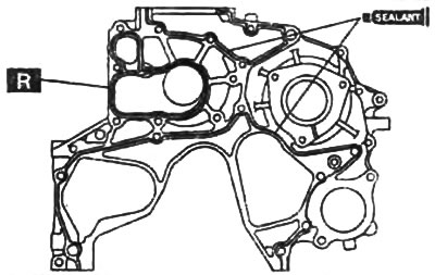
3. Tighten the fuel injection pump drive gear housing mounting bolts in two or three passes in the sequence shown in the figure.
Note on installation of fuel injection pump drive gear components
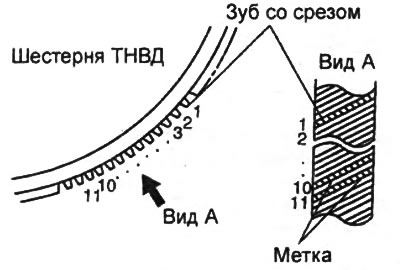
1. Place a mark on the tooth of the injection pump gear that has a large beveled cut.
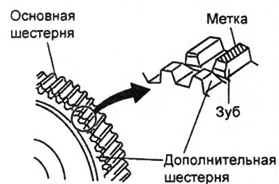
2. Apply marks to the 10th and 11th teeth of the main gear of the fuel injection pump, moving clockwise from the tooth with the large bevel cut.
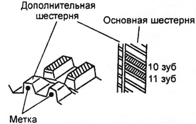
3. Make sure that the 10th and 11th teeth of the main gear of the injection pump are aligned with the teeth of the additional gear and make marks on the teeth of the additional gear.
4. Turn the engine crankshaft clockwise so that the piston in the first cylinder is in the TDC position on the compression stroke.
5. Turn the flywheel and set the piston in the first cylinder to 30° before TDC (13 teeth).
6. Align the marks on the gears of the fuel injection pump drive mechanism with the installation marks, as shown in the figure "Alignment of marks on the gear mechanism of the fuel injection pump drive".
7. Remove the bolt securing the additional gear to the main gear of the fuel injection pump.
8. Use the locking device to secure the flywheel.
9. Tighten the bolts securing the fuel injection pump drive mechanism gears.
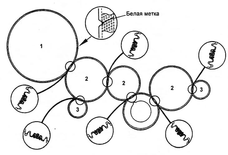
Alignment of marks on the fuel injection pump drive gear mechanism.
1 - fuel injection pump gear,
2 - intermediate gear,
3 - balance shaft gear.
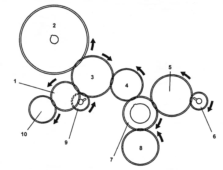
Drive gears.
1 - vacuum pump gear,
2 - fuel injection pump gear,
3 - intermediate gear No.2,
4 - intermediate gear No.1,
5 - intermediate gear No.3,
6, 9 - balance shaft gear,
7 - crankshaft gear,
8 - oil pump gear,
10 - power steering pump gear.
Note on installing the fuel injection pump drive gear cover
1. Apply a layer of engine oil to the lip of the oil seal.
2. Press in the seal of the fuel injection pump drive gear cover using a mandrel of suitable diameter and a hammer.
- Pressing depth: 0-0.4 mm
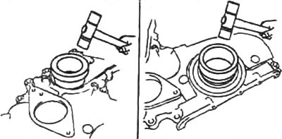
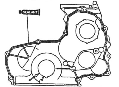
3. Apply silicone sealant to the contact surfaces of the fuel injection pump drive gear cover in the places indicated in the figure.
- Sealant thickness: 2-3 mm
Note: The parts must be installed within the time specified in the sealant application instructions. Otherwise, the sealant must be removed and reapplied.
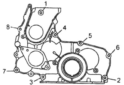
4. Tighten the fuel injection pump drive gear cover mounting bolts in two or three passes in the sequence shown in the figure.
Note on installing the crankshaft pulley and fuel injection pump pulley
Using the locking device, secure the flywheel and install the pulley.