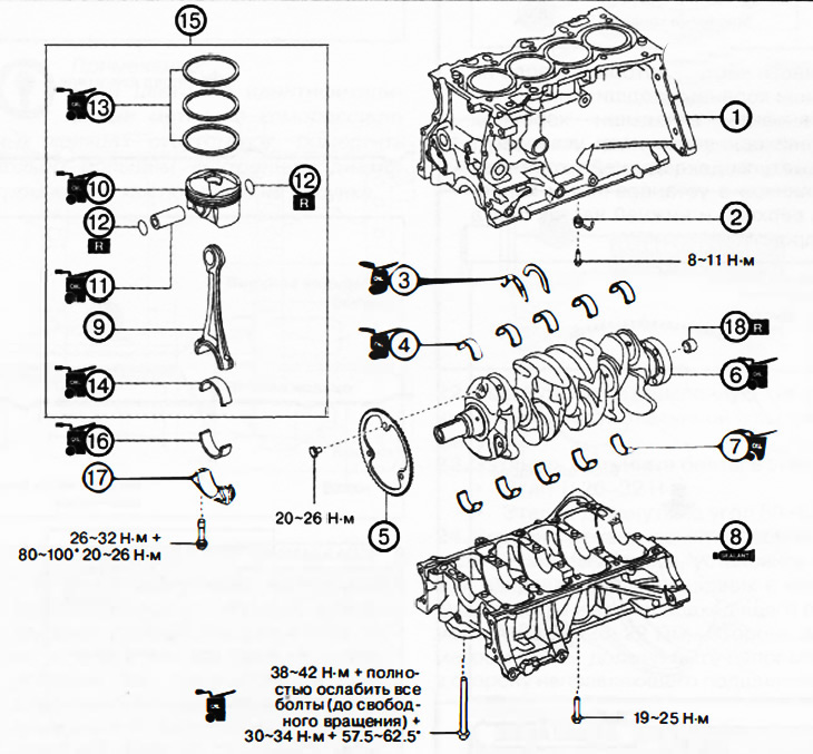
1. Cylinder block.
2. Oil nozzles.
3. Thrust half rings.
4. Top liners of radical bearings.
5. Impulse disk.
6. Crankshaft.
7. Lower shells of main bearings.
8. The lower part of the cylinder block.
9. Connecting rod.
10. Piston.
11. Piston pin.
12. Retaining rings.
13. Piston rings.
14. Upper connecting rod bearing.
15. Piston with connecting rod assembly.
16. Lower connecting rod bearing.
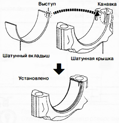
17. Connecting rod cap.
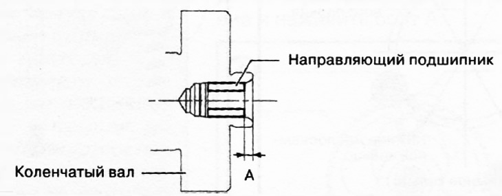
18. Guide bearing (ITUC).
Note:
: replace the part with a new one after each removal.
: apply oil.
: apply sealant.
1. Install oil nozzles on the cylinder block.
Attention.
- If the thrust washers and main bearing shells are reused, they must be reinstalled in the same positions in the same direction as they were before removal to prevent damage from seized or burnt bearings.
- To prevent damage to the engine during assembly, apply engine oil to the friction surfaces.
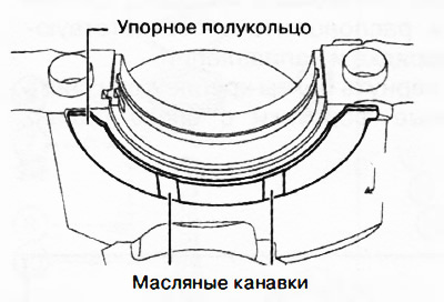
2. Apply clean engine oil to the thrust washers.
3. Install thrust half rings with oil grooves towards the friction surfaces.
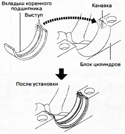
4. Apply clean engine oil to the main bearing shells.
5. Install the main bearing shells by aligning the mounting tabs of the main bearing shells with the mounting grooves in the top and bottom of the cylinder block.
Attention. Do not place the crankshaft on a flat surface because the diameter of the impulse disc mounted on the crankshaft is larger than the crankshaft balancers. Place wooden blocks or other suitable objects under both ends of the crankshaft so that the impulse disk does not directly touch a flat surface.
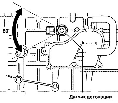
6. If it was removed, install the impulse disk on the crankshaft:
Set the groove of the impulse disk to the position shown in the figure and screw on the bolt A.
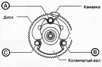
Fit bolt B.
Install bolt C and tighten all bolts to 20-26 Nm in sequence C, B and A.
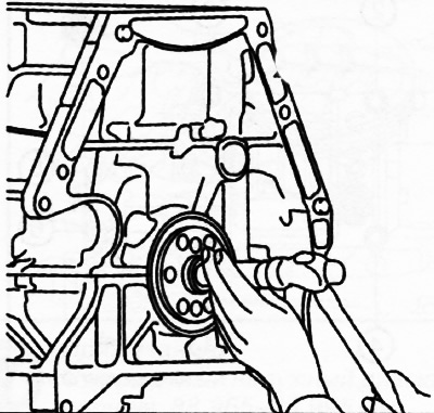
7. Install the crankshaft to the top of the cylinder block.
8. Completely clean the contact surfaces of the lower and upper parts of the cylinder block from oil, sealant residues and other contaminants.
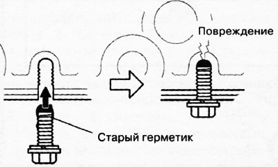
9. In case of reuse of bolts of fastening of the bottom part of the block of cylinders to remove the rests of sealant from bolts.
Attention.
- Apply silicone sealant in an even, continuous bead.
- To prevent premature curing of the silicone sealant, install the front cover on the engine within 10 minutes of applying the sealant. Tighten the fastening bolts immediately.
- If the bolt with hardened sealant is tightened, it may cause a crack in the cylinder head or cylinder block.
10. Apply silicone sealant to the bottom of the cylinder block as shown.
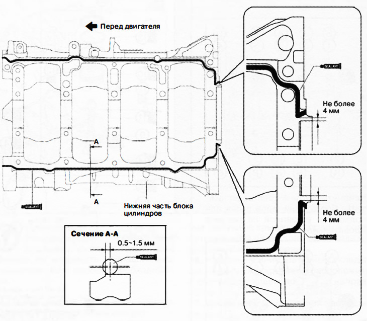
Note: Sealant bead thickness: 2-6mm.
11. Install the lower part of the cylinder block.
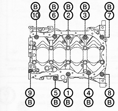
12. Tighten the bolts securing the lower part of the cylinder block:
Apply clean engine oil to the seating surfaces and threads of bolts A on the bottom of the cylinder block.
Tighten the bolts A of the lower part of the cylinder block in the sequence shown in the figure.
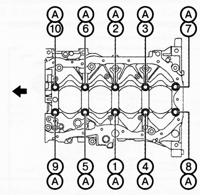
Stage 1: 38-42 Nm
Step 2: loosen all bolts (before free rotation)
Stage 3: 30-34 Nm
Step 4: Reach 57.5-62.5°
Tighten bolts B of the lower part of the cylinder block in the sequence shown in the figure to a torque of 19-25 Nm.
13. After the silicone sealant comes out in the socket of the crankshaft rear oil seal, remove this excess. If the silicone sealant does not come out, remove the lower part of the cylinder block and reapply the sealant.
14. Apply clean engine oil to the piston pin.
15. Insert the connecting rod into the piston and connect them with the piston pin.
Note: Pay attention to the correct direction of the connecting rod and piston relative to each other.
Attention. When installing, do not compress the piston pin circlip more than necessary (up to diameter less than 20.66 mm).
16. Using needle nose pliers, install new piston pin circlips into the piston.
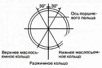
Note: It is not necessary to place an expansion ring lock between the upper and lower wiper rings.
17. Install the oil scraper ring so that the locks of the oil scraper rings do not overlap each other.
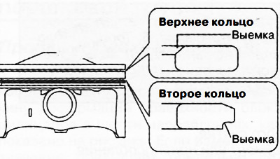
Note: Install piston rings so that the color identification marks on the compression rings are visible on the right side of each piston ring lock.
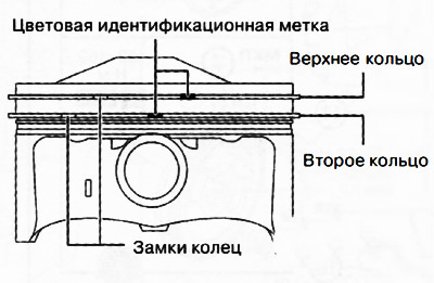
Note: If there are no color identification marks on the compression rings, place the ring with the larger ID up as shown.
Attention.
- If the connecting rod bearings are reused, they must be reinstalled in the same places in the same direction as they were before removal, to prevent damage due to jamming or burning of the bearings.
- To prevent damage to the engine during assembly, apply engine oil to the friction surfaces.
18. Apply clean engine oil to the connecting rod bearings.
19. Install the connecting rod bearings by aligning the mounting lug of the bearing with the mounting groove of the connecting rod or connecting rod cap.
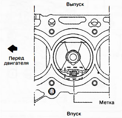
20. Insert the piston into the cylinder so that the mark on the piston bottom is on the intake side.
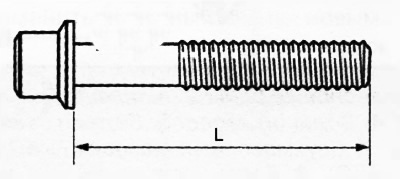
21. Check the length of the connecting rod bolts (see related section below).
22. Align the broken, uneven surface of the connecting rod cap with the connecting rod
23. Tighten the connecting rod bolts in steps:
- Stage 1: 26-32 Nm.
- Stage 2: pull up to an angle of 80-100°.
24. Versions with manual transmission: if removed, install a new pilot bearing with a hammer and bushing of the appropriate size A160M7 (20-22 mm). The 20 mm diameter side must face the pilot bearing.
Note. Depth of pressing the guide bearing into the crankshaft (A): 1.5-2.5 mm.
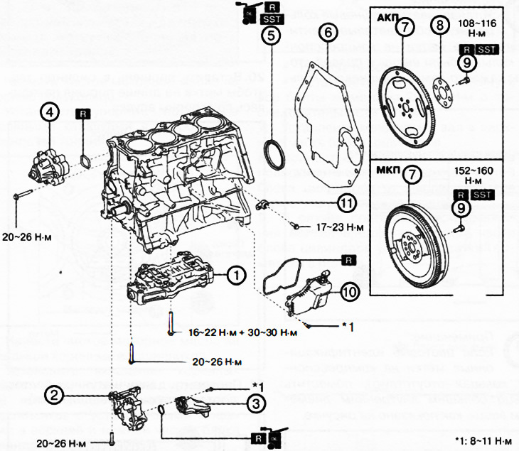
1. Balancing block.
2. Oil pump.
3. Oil intake with strainer.
4. Water pump.
5. Rear crankshaft oil seal.
6. End plate.
7. Dual mass flywheel (ITUC) / drive flange (AKP).
8. Platter (AKP).
9. Dual-mass flywheel mounting bolts (ITUC) /drive flange (AKP).
10. Oil separator.
11. Knock sensor.
Note:
: replace the part with a new one after each removal.
: use a special tool or attachments.
: apply oil.
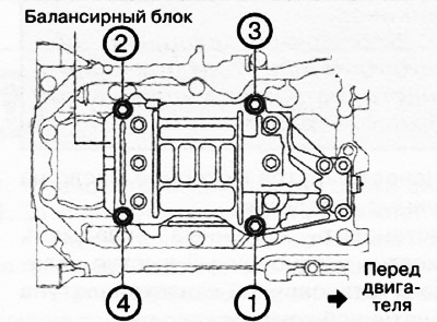
25. Install the balancing block on the engine:
Tighten the bolts in the sequence shown in the figure.
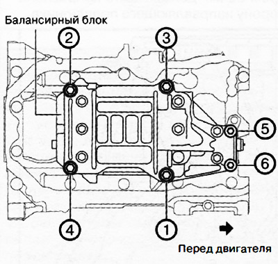 | 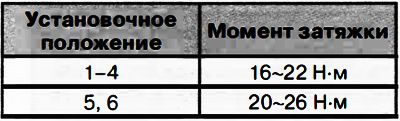 |
Re-tighten the bolts in the sequence shown in the figure to a torque of 30-36 Nm.
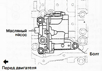
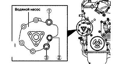
26. Install the oil pump on the engine:
Install the three screws shown in the figure.
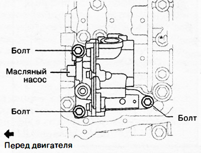
Tighten the two bolts shown in the figure to a torque of 20-26 Nm. The tightening sequence does not matter.
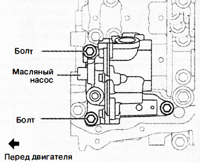
Finally, tighten the remaining bolt to 20-26 Nm.
27. Install the oil intake with a strainer.
28. Insert a new gasket into the water pump groove.
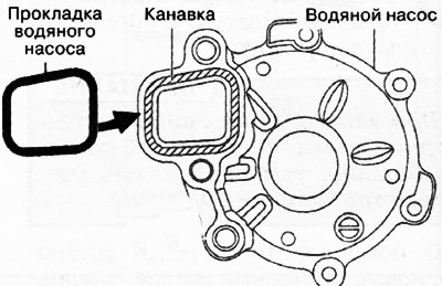
Attention. Install the water pump gasket in the correct position as shown in the illustration. Otherwise, coolant leaks and various engine damage may occur.
29. Install water pump.
30. Tighten the bolts in the sequence shown in the figure to a torque of 20-26 Nm.
31. Install the crankshaft rear oil seal (see relevant section of this chapter).
32. After installing the end plate, crimp parts A and B as shown.
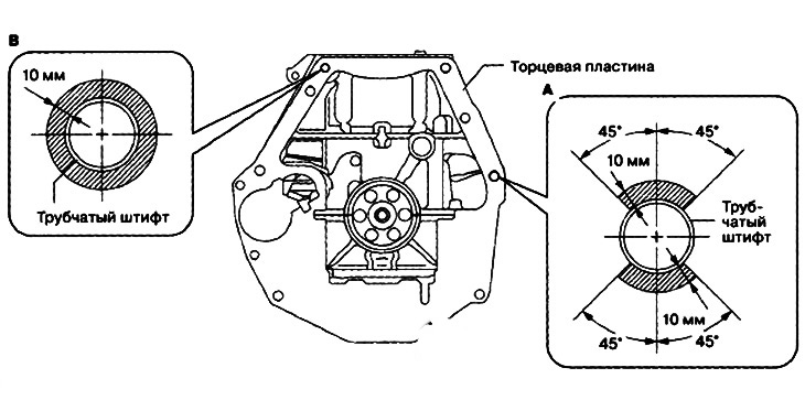
Note:
- Compression depth: 0.1-1.0 mm.
- Crimping width: 0.5-10.0 mm.
33. After crimping, check that the end plate is not damaged.
34. Install the flywheel (ITUC) (see chapter «Clutch») or drive flange with platter (AKP).
35. Install the oil separator on the engine.
36. Install knock sensor.
Note:
- Check for foreign material between knock sensor and cylinder block.
- The knock sensor connector must be within the range shown in the illustration.