


Caution: Do not disassemble the oil pump, water pump and balancer block as they are precision units.
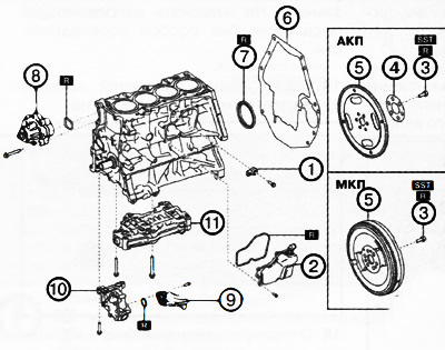
1. Knock sensor.
2. Oil separator.
3. Dual mass flywheel (MT)/drive flange (AT) mounting bolts.
4. Support disk (automatic transmission).
5. Dual mass flywheel (manual transmission) or drive flange (automatic transmission).
6. End plate.
7. Rear crankshaft oil seal.
8. Water pump.
9. Oil intake with mesh filter.
10. Oil pump.
11. Balancing block.
Note:
: replace the part with a new one after each removal.
: use a special tool or device.
Article is available on the website: www.mazbook.ru
1. Remove the engine from the car.
2. Remove the accessory drive belts, as well as the timing chain and oil pump drive chains.
3. Remove the cylinder head and oil pan from the engine.
4. Loosen the mounting bolt and remove the knock sensor.
5. Loosen the mounting bolts and remove the oil separator.
6. Fix the flywheel/drive flange ring gear using a special device as shown in the figure.
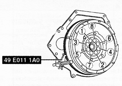
7. Gradually loosen the bolts in the sequence shown in the figure and remove the dual mass flywheel (manual transmission) or the drive flange with the support disk (automatic transmission).
8. Remove the end plate from the engine block.
9. Remove the rear crankshaft oil seal.
10. Loosen the mounting bolts and remove the water pump from the engine cylinder block.
11. Remove the oil intake and oil pump from the engine cylinder block.
12. Loosen the mounting bolts and remove the balance block.
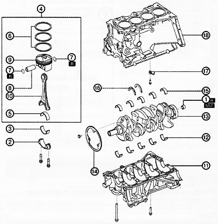
1. Guide bearing (versions with manual transmission).
2. Connecting rod cover.
3. Lower connecting rod bearing.
4. Piston with connecting rod assembly.
5. Upper connecting rod bearing.
6. Piston rings.
7. Retaining rings.
8. Piston pin.
9. Piston.
10. Connecting rod.
11. Lower part of the cylinder block.
12. Lower crankshaft main bearing shells.
13. Crankshaft.
14. Pulse disk.
15. Upper main bearing shells of the crankshaft.
16. Thrust half rings.
17. Oil nozzle.
18. Cylinder block.
Note:
: replace the part with a new one after each removal.
: use a special tool or device.
13. Versions with manual transmission: if necessary, use a special tool to remove the guide bearing from the crankshaft.
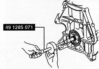
Note: The pilot bearing should only be removed for replacement. Do not remove the pilot bearing unless absolutely necessary.
14. Before removing the connecting rod cap, check the connecting rod side clearance.
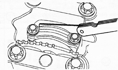
15. Loosen the connecting rod bolts and remove the connecting rod caps. Arrange the removed connecting rod caps in the order corresponding to the engine cylinders and in the correct direction.
16. Remove the lower connecting rod bearings from the connecting rod caps and arrange them in the appropriate order and direction.
17. Remove carbon deposits from the top of the cylinder.
Note: Before removing the piston with connecting rod from the engine, check the oil clearance in the connecting rod bearing (see the relevant section below).
18. Remove the piston with the connecting rod assembly through the top of the cylinder.
19. Remove the upper connecting rod bearings and arrange them in the proper order and direction.
20. Using special pliers, remove the piston rings from the piston.
21. Make sure that the lower part of the connecting rod falls freely under its own weight without resistance when turning the piston.
22. Using flat-head screwdrivers, remove the retaining rings.
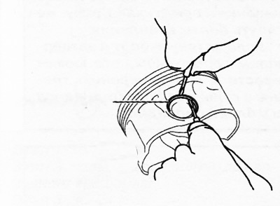
23. Remove the piston pin from the piston and separate the piston and connecting rod.
Note: Before removing the lower part of the cylinder block, check the crankshaft axial play (see the relevant section below).
24. Loosen the bolts B securing the lower part of the cylinder block in two or three steps in the sequence shown in the figure.
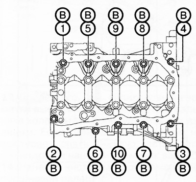
25. Loosen bolts A securing the lower part of the cylinder block in two or three steps in the sequence shown in the figure.
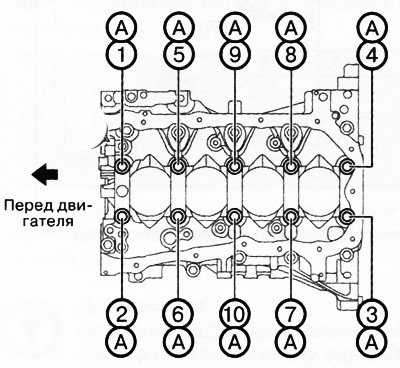
26. Using a screwdriver wrapped in cloth, gradually separate the sealant and remove the lower part of the cylinder block.
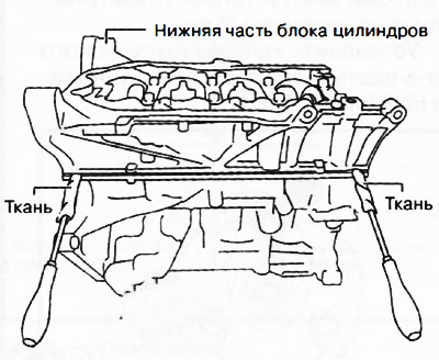
Attention.
- Do not apply excessive force to the screwdriver. Otherwise, the lower part of the cylinder block may be damaged.
- Be careful not to scratch or damage the sealing surfaces, otherwise oil leaks may occur.
27. Remove the lower crankshaft main bearing shells from the bottom of the cylinder block and arrange them in the proper order and direction.
28. Remove the crankshaft from the engine cylinder block.
Caution: Do not place the crankshaft on flat surfaces because the diameter of the pulse disk installed on the crankshaft is larger than the size of the crankshaft balancers. Place wooden blocks or other suitable objects under both ends of the crankshaft to prevent the pulse disk from directly touching the flat surface.
29. If necessary, loosen the mounting bolts and remove the pulse disk from the crankshaft.
30. Remove the upper crankshaft main bearing shells and thrust half rings from the cylinder block and arrange them in the appropriate order and direction.
31. Loosen the mounting bolts and remove the oil injectors from the cylinder block.