


Remove the oil pan.
Remove the oil filter.
Remove the oil cooler.
Remove the knock sensor.
Remove the oil separator.
Remove the thermostat.
Remove the coolant pump.
Remove the mesh oil filter.
Remove the oil pump.
Remove the flywheel (models with manual transmission). To remove the drive disc (models with automatic transmission):
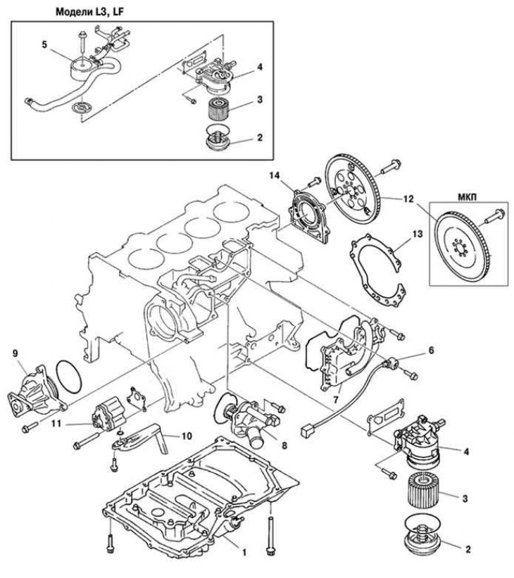
Fig. 2.127. Components of the first stage of disassembling the cylinder block: 1 – oil pan; 2 – oil filter cover; 3 – oil filter; 4 – Oil filter adapter; 5 – oil cooler; 6 – knock sensor; 7 – oil separator; 8 – thermostat; 9 – coolant pump; 10 – mesh oil filter; 11 – oil pump; 12 – flywheel (model with manual transmission), leading disk (models with automatic transmission); 13 – end disk (model with manual transmission); 14 – rear oil seal
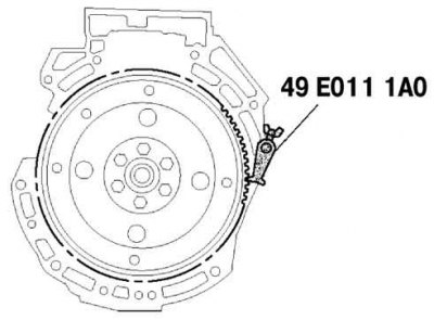
Fig. 2.128. Holding the crankshaft from turning using a special device
- hold the crankshaft from turning using a special device (fig. 2.128);
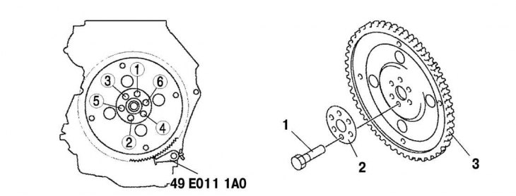
Fig. 2.129. Components of the drive disk and the order of unscrewing the mounting bolts: 1 – bolt; 2 – adapter; 3 – leading disk
- unscrew the bolts in several steps in the order shown in Figure 2.129.
Remove the end disc (models with manual transmission).
Remove the rear oil seal.
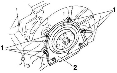
Fig. 2.130. Removing the rear crankshaft oil seal: 1 – bolts; 2 – oil seal
Unscrew the six bolts securing the rear oil seal and remove the oil seal (fig. 2.130).
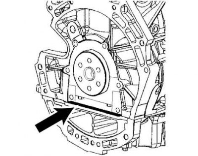
Fig. 2.131. Places of sealant application
(The article is copied from the resource: «mazbook.ru»)
Apply organosilicon sealant to the mating surfaces in the location shown in Figure 2.131. The diameter of the application point is 0.4–0.6 mm.
Apply clean engine oil to the sealing lip of the new oil seal.
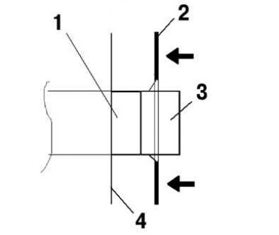
Fig. 2.132. Crankshaft rear oil seal installation diagram: 1 – crankshaft; 2 – rear oil seal; 3 – installation device; 4 – cylinder block
Install and press the rear oil seal using the installation tool as shown in Figure 2.132.
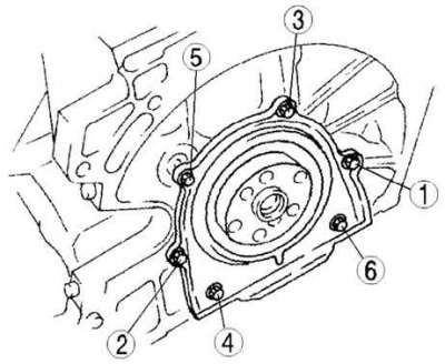
Fig. 2.133. Tightening order of the crankshaft rear oil seal mounting bolts
Tighten the rear oil seal mounting bolts in the order shown in Figure 2.133 to a tightening torque of 8.0–11.5 N·m.
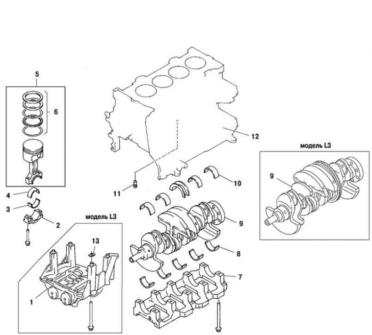
Fig. 2.134. Components of the second stage of disassembling the cylinder block: 1 – balancing block (L3, L3 with variable valve timing mechanism); 2 – connecting rod cover; 3 – lower connecting rod bearing; 4 – upper connecting rod bearing; 5 – connecting rod and piston assembly; 6 – piston ring; 7 – main bearing cap; 8 – lower main bearing, thrust bearing; 9 – crankshaft; 10 – upper main bearing, thrust bearing; 11 – oil spray nozzle valve; 12 – cylinder block; 13 – adjusting gasket
Remove the balancing block (l3, L3 engines with variable valve timing mechanism, see Fig. 2.134).
Remove the connecting rod cap. Before removing the connecting rod cap, check the connecting rod side clearance (see below). Remove the connecting rod bolt from the connecting rod cap by hitting the bolt with a nylon hammer.
Remove the lower connecting rod bearing.
Remove the upper connecting rod bearing.
Remove the connecting rod and piston assembly.
Remove the piston rings.
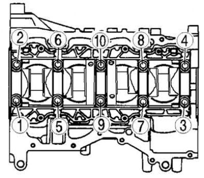
Fig. 2.135. Procedure for loosening the main bearing cap mounting bolts
Before removing the main bearing cap, check the crankshaft axial clearance. Loosen the main bearing cap mounting bolts in two or three steps in the order shown in Figure 2.135.
Remove the lower main and thrust bearings.
Remove the crankshaft.
Remove the upper main bearings, thrust bearings.
Remove the oil spray nozzle valve.