


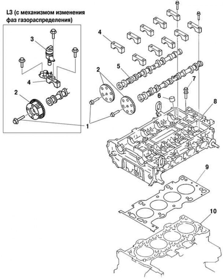
Fig. 2.120. Components of the first stage of disassembling the cylinder head: 1 – camshaft sprocket mounting bolts; 2 – camshaft sprockets; 3 – Oil control valve (OCV)(L3); 4 – camshaft covers; 5 – camshafts; 6 – valve tappet; 7 – cylinder head mounting bolt; 8 – cylinder head; 9 – cylinder head gasket; 10 – cylinder block
Loosen the camshaft sprocket mounting bolts (see fig. 2.120) (variable valve timing mechanism mounting bolt), as shown in Figure 2.121.
Remove the camshaft sprockets. The variable valve timing actuator (L3 with variable valve timing mechanism).
Remove the oil control valve (OCV) (L3 with variable valve timing mechanism).
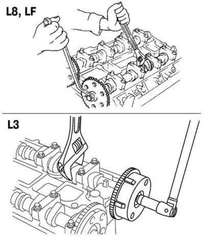
Fig. 2.121. Loosening the camshaft sprocket mounting bolts
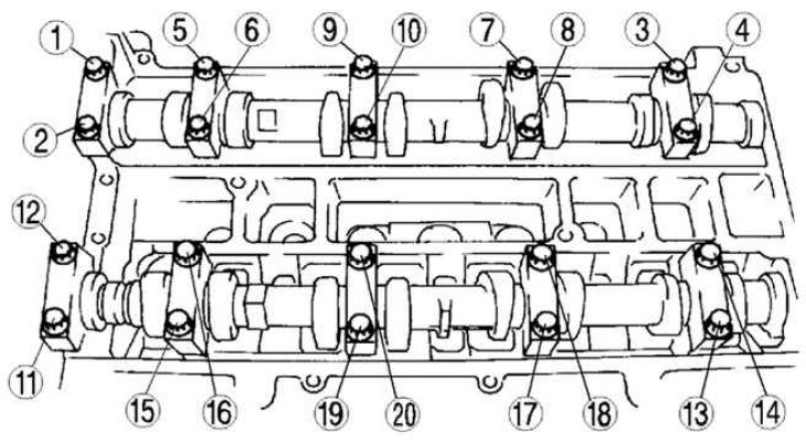
Fig. 2.122. Sequence of loosening the camshaft bearing cap bolts
Remove the camshaft bearing caps by loosening the mounting bolts in three steps in the order shown in Figure 2.122.
Note: Before removing the camshaft bearing caps, check the camshaft end play and camshaft bearing clearances (see below). The camshaft bearing caps are numbered to ensure proper reassembly. After removal, keep the caps together with the cylinder head from which they were removed. Do not mix the caps.
Remove the camshafts.
Remove the valve lifters.
Note: The valve lifters are numbered to ensure proper reassembly. After removal, keep the valve lifters together with the cylinder head from which they were removed. Do not mix valve lifters.
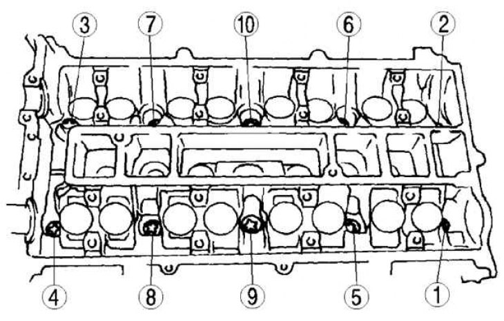
Fig. 2.123. Sequence of loosening the cylinder head mounting bolts
Loosen the cylinder head mounting bolts in two or three steps in the order shown in Figure 2.123.
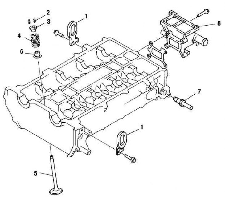
Fig. 2.124. Components of the second stage of disassembling the cylinder head: 1 – engine lifting eye; 2 – valve cracker; 3 – upper valve spring plate; 4 – valve spring; 5 – valve; 6 – oil deflector cap; 7 – recirculation system tube; 8 – cooling system outlet pipe housing
Remove the engine lifting eyes (fig. 2.124).
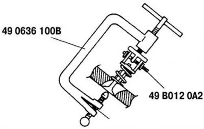
Fig. 2.125. Removing the valve cracker
Using special tools, remove the valve crackers (fig. 2.125).
Remove the upper valve spring retainer.
Remove the valve spring and valve.
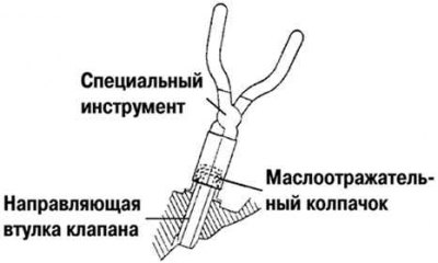
Fig. 2.126. Removing the oil deflector cap
Using a special tool, remove the oil deflector cap (fig. 2.126).
Remove the recirculation system tube.
Remove the cooling system outlet pipe housing.