
Attention.
- Hot engine and oil can cause burns. Be careful not to burn yourself when removing/installing various components.
- Fuel vapors are dangerous. They are highly flammable, causing serious injury and equipment damage. Keep sparks or open flames away from fuel.
- Leaks and leaks in fuel lines are dangerous. Fuel can ignite and cause equipment damage, serious injury or even death. Fuel can cause skin and eye irritation. To prevent this, observe the safety regulations when handling fuels and lubricants.
- If the camshaft is rotated after the timing chain has been removed, when the piston is at top dead center, the valves may hit the piston crown, causing engine damage. When rotating the camshaft with the drive chain removed, it is necessary to set all the engine pistons to the middle position.
Removing the cylinder head
1. Disconnect the negative battery terminal.
2. Remove the decorative engine cover.
3. Remove ignition coils/ion sensors.
4. Remove the front protective tray #2.
5. Remove mudguard.
6. Remove attachment drive belts.
7. Drain engine oil.
8. Drain coolant.
9. Remove intake manifold.
10. Direct the exhaust manifold towards the rear of the vehicle.
11. Disconnect the upper and lower radiator hoses.
12. Remove the vacuum pump.
13. Remove the high pressure fuel pump with rear casing.
14. Disconnect heater hoses from inlet and outlet ports.
15. Remove the engine oil pan.
16. Remove the timing chain with damper (see relevant section earlier in this chapter).
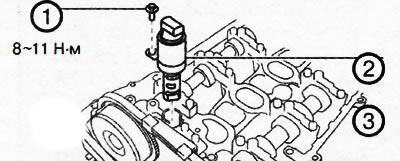
17. Unscrew the fastening bolt (1) and remove the oil control valve (OCV) (2).
18. To disconnect from a head of the block of cylinders and to remove all pipelines and hoses of system of cooling.
1. Water hose (if equipped).
2. The inlet pipeline of the cooling system.
3. Camshafts.
4. Rocker arms.
5. Cylinder head.
6. Laying of a head of the block of cylinders.
19. Unscrew the bolts of the camshaft covers in two or three approaches in the sequence shown in the figure, then remove the covers and remove the camshafts from the cylinder head.
20. Remove the rocker arms from the cylinder head and arrange them in the order corresponding to the cylinders so that they can be installed in their places during assembly.
21. Temporarily install an oil pan to support the engine from under the vehicle.
Attention.
To prevent deformation of the oil pan, support the engine as follows:
- When using the engine jack, place a piece of rubber of suitable size (about 20 mm thick) between lift and oil pan.
- When using a garage jack, place a piece of rubber of a suitable size (about 20 mm thick) on the base plate resting on the oil pan.
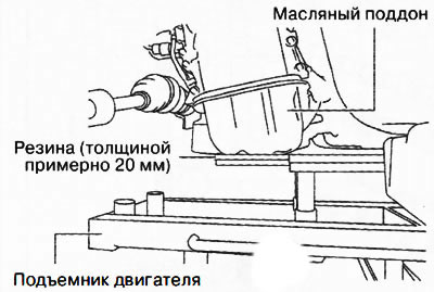
22. Support the engine (oil pan) a special engine lift or a garage jack.
23. Remove the chain of the traverse, on which the engine is suspended, and take it to the side.
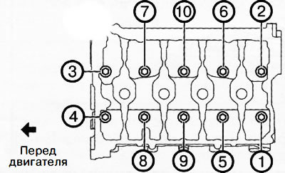
24. To turn away bolts of a head of the block of cylinders in two or three approaches in the sequence specified in drawing.
25. Remove the cylinder head.
26. Remove the cylinder head gasket and replace it with a new one.
Installing the cylinder head
1. Thoroughly clean the contact surfaces of the cylinder block and block head.
2. Install a new cylinder head gasket
3. Install the cylinder head on the engine.
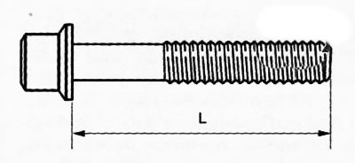
Attention. If length (L) cylinder head bolt exceeds the limit (146.5 mm), you need to replace it with a new one.
4. If cylinder head bolts are reused, apply engine oil to the seating surface of the bolt head and cylinder head.
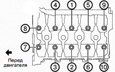
5. Tighten the cylinder head bolts in four stages in the sequence shown in the figure:
- Stage 1: 13-17 Nm
- Stage 2: 43-47 Nm
- Stage 3: 85-95°
- Stage 4: 85-95°
6. Install the traverse chain to support the engine.
7. Remove the engine jack or garage jack from under the engine oil pan.
8. Remove the temporarily installed oil pan.
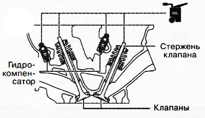
9. Apply engine oil to the hydraulic lifters and valve stem ends.
10. Set the rocker arms to their original positions, which they occupied before removal.
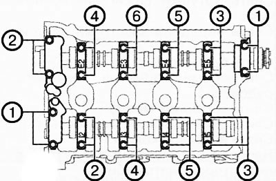
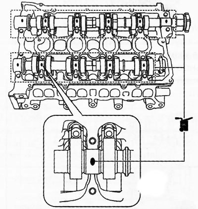
11. Apply gear oil (SAE 90 or similar) or engine oil on the center of each bearing in the cylinder head as shown.
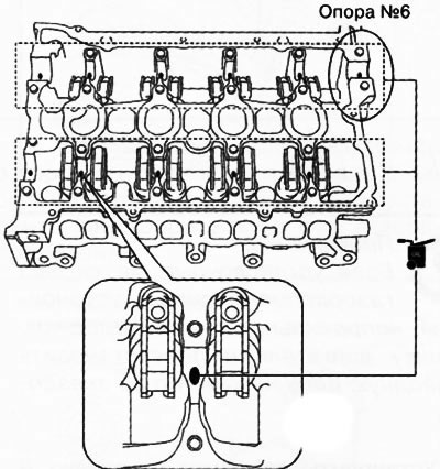
Attention. No more than 0.05 ml of oil should be applied to support No. 6.
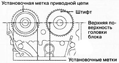
12. Install the camshafts, aligning the alignment marks as shown in the figure.
13. Apply gear oil (SAE 90 or similar) or engine oil on the center of each camshaft journal as shown.
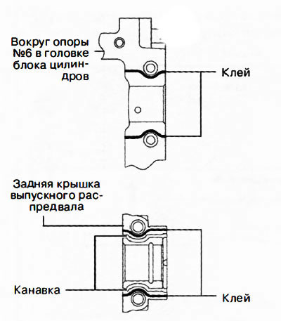
14. Apply adhesive (Loctite 962T) around support No. 6 of the cylinder head or on the rear cover of the exhaust camshaft.
Attention. Make sure that the adhesive does not get on the camshaft journal.
Note: Adhesive bead width: 0.5-1.5 mm.
15. Install the camshaft covers in numerical order (according to the markings on the lids) and evenly screw on the cover bolts in two or three passes in the sequence shown in the figure.
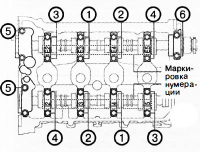
16. Tighten the camshaft cover bolts in two stages in the sequence shown in the figure: first to a torque of 3.0-6.0 Nm, and then to a torque of 8-11 Nm.
17. Remove the remaining sealant from the bolt holes in the cylinder block on the side of the rack of the inlet pipe of the cooling system.
18. Apply coolant to the O-rings.
Attention. Don't apply too little (motor, transmission, etc.) on the O-rings of the water inlet pipe. Otherwise, the material of the O-rings may be damaged, resulting in a leak.
19. Install the O-ring on the inlet pipe of the cooling system.
20. Insert the cooling system inlet into the water pump, being careful not to damage the O-ring.
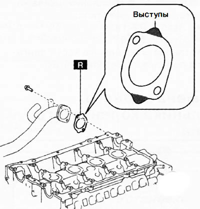
21. Install the gasket for the inlet pipe of the cooling system so that its protrusions are located as shown in the figure.
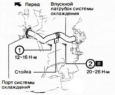
22. Tighten the bolts in the sequence shown in the figure.
23. Install the remaining parts in the reverse order of removal.
24. Fill in the required amount of engine oil of the correct grade (see chapter "Lubrication system").
25. Fill with coolant.
26. Start the engine and check the following:
- Leaks in engine oil and coolant.
- Beating and touching of pulleys and belts.
- Ignition timing and idle speed.
- Compression in the cylinders.