
2. Turn off the engine and remove the air filter assembly from the engine. Label all hoses and wires to the air filter for ease of installation (photo).
Mark with adhesive tape the vacuum hoses that connect to the air filter so as not to mix them up during installation
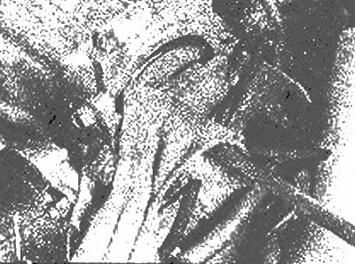
3. Remove the crankcase ventilation valve and spark plug wires from the camshaft cover. Use a piece of wire to tie up the throttle cable outside of the work area.
4. Remove the camshaft cover bolts, being careful not to lose the washers (photo).

Remove the camshaft cover bolts | 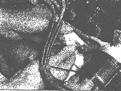
Be sure to remove the camshaft cover bolt washers |
5. Wrap the end of a large screwdriver in a rag and use it to gently pry the camshaft cover off (photo). Remove the cover from the engine and remove the gasket.
Pry off the camshaft cover with a screwdriver, the end of which is wrapped in a rag, so as not to damage the aluminum housing
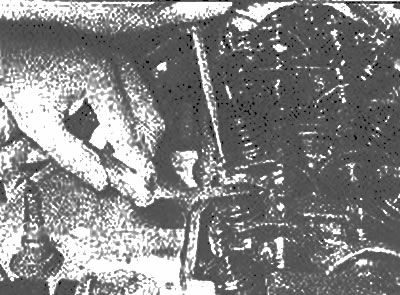
6. Place #1 piston at top dead center (TDC) during compression. To do this, number the wires of the spark plugs, then remove all the spark plugs from the engine. Locate the #1 cylinder spark plug wire and trace it to the distributor. Place the number 1 on the distributor housing directly below the #1 spark plug wire clamp on the distributor cap. Do the same with the rest of the wires, marking their number on the distributor body, then remove the cover with the wires from the gel distributor (photo).
Mark the distributor wires with adhesive tape | 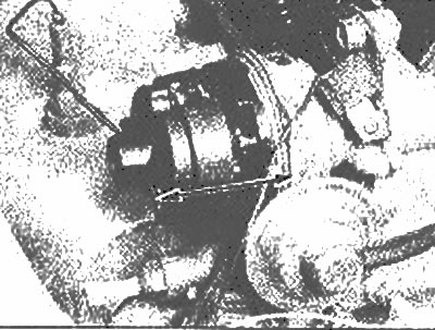
Mark the location of the distributor wire on the body |
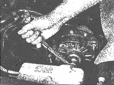
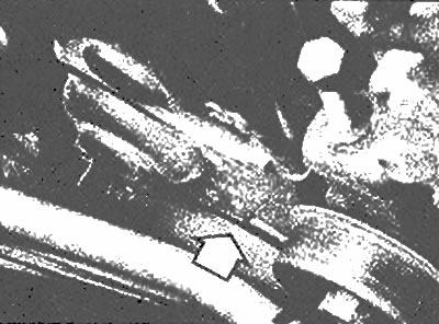
7. Slowly turn the crankshaft clockwise by installing a wrench or socket on the large bolt on the front of the crankshaft or (if the drive belt is tight enough) on the generator so that the notch on the crankshaft pulley is aligned with the pointer (photo). The slider should be directed to the number 1, which you put on the distributor housing (photo). If not, rotate the crankshaft 360°clockwise. If the slider now points to the number 1 on the distributor housing, then piston No. 1 is at TDC on the compression stroke, and therefore the clearances of the intake and exhaust valves of cylinder No. 1, the inlet valve of cylinder No. 2 and the exhaust valve of cylinder No. 3 can be checked and adjusted. The intake valves are on the back of the engine (facing the thermal insulation probe), and graduation - on its front side.
After removing the spark plugs, install a socket or wrench on the alternator nut and crank the engine (if the drive belt is tensioned correctly) | 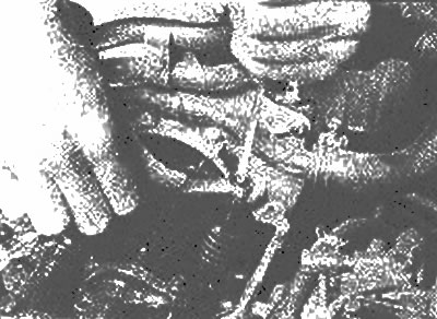
The notch of the crankshaft pulley is aligned with the TDC mark |
The contact of the distributor slider is directed to the spark plug wire mark No. 1 (arrow) on the body (those. cylinder #1 is in BMT)
8. Insert a suitable stylus (see specs) between the valve stem and rocker arm. If the feeler gauge fits between them with little effort, the gap is correct and no adjustment is required.
9. If the feeler gauge does not enter this gap or enters too freely, loosen the adjusting screw locknut and gently tighten or loosen the adjusting screw to adjust the gap (photo).
10. While holding the adjusting screw stationary with a screwdriver, securely tighten the locknut (photo). Recheck the gap to make sure it hasn't changed.
11. Turn the crankshaft a full turn (360°), which will bring the #4 cylinder piston to top dead center on the compression stroke. Check this by making sure the slider points to the #4 spark plug wire position. Check and adjust the clearance of cylinder #2 exhaust valve, cylinder #3 tasty valve, and cylinder #4 intake and exhaust valves.
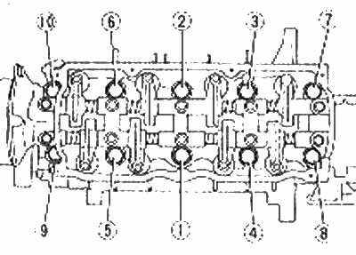
12. Check up the moments of an inhaling of bolts of fastening of a head of the block of cylinders (engine hot), using a torque wrench. Loosen one bolt a quarter of a turn, then tighten it to the specified torque specifications. Repeat the procedure on all cylinder head bolts in the sequence shown in the illustration.
13. Install the camshaft cover (use a new gasket) and tighten the mounting bolts evenly and securely with the specified tightening torque (see Specifications Section 2A).
14. Install spark plugs, distributor cap and spark plug wires. Install the air filter and connect all associated hoses, power connectors and vacuum lines.
15. Start the engine and check the tightness of the connection between the camshaft cover and the cylinder head.