


Car fuel injection system Mazda BT-50 1

Fuel injection system — device
Diagram of the fuel system, air intake system and exhaust system. 1 - oxidizing neutralizer, 2 - glow plug, 3 - nozzle, 4 - coolant temperature sensor, 5 - crankshaft...
Diagram of the fuel system, air intake system and exhaust system. 1 - oxidizing neutralizer, 2 - glow plug, 3 - nozzle, 4 - coolant temperature sensor, 5 - crankshaft...

Precautions when working with the fuel system
Attention: Before performing any repair work on the fuel system, be sure to disconnect the cable from the negative terminal of the battery. Do not smoke or use open...
Attention: Before performing any repair work on the fuel system, be sure to disconnect the cable from the negative terminal of the battery. Do not smoke or use open...
Before carrying out repair work
1. To relieve pressure in the fuel tank, open the fuel tank filler cap. 2. Disconnect the fuel hose, after covering it with a rag. 3. Install the plug into the fuel hose.
1. To relieve pressure in the fuel tank, open the fuel tank filler cap. 2. Disconnect the fuel hose, after covering it with a rag. 3. Install the plug into the fuel hose.

After the repair work has been completed
1. Check all fuel hoses and tubes for cracks or damage. 2. When connecting the fuel hoses, refer to the figure "Location of fuel system components in the engine...
1. Check all fuel hoses and tubes for cracks or damage. 2. When connecting the fuel hoses, refer to the figure "Location of fuel system components in the engine...

Removal air from the fuel system
Caution: If the fuel tank has been repaired or other repair work has been performed during which the fuel has been completely drained from the fuel tank, or if the fuel...
Caution: If the fuel tank has been repaired or other repair work has been performed during which the fuel has been completely drained from the fuel tank, or if the fuel...

Removal water from the fuel system
Note: When the diesel engine is running, the fuel filter separates water from diesel fuel to prevent damage to fuel system components "Common Rail". When about 0.13 l of...
Note: When the diesel engine is running, the fuel filter separates water from diesel fuel to prevent damage to fuel system components "Common Rail". When about 0.13 l of...
Fuel injection advance angle
The injection advance angle on these engines is adjusted automatically by the engine control unit. Check the injection advance angle using a scanner.
The injection advance angle on these engines is adjusted automatically by the engine control unit. Check the injection advance angle using a scanner.

High pressure fuel pump — removal and installation
Warning: Do not disassemble or repair the fuel injection pump yourself. Fuel injection pump repairs should only be performed in specialized Bosch service centers that...
Warning: Do not disassemble or repair the fuel injection pump yourself. Fuel injection pump repairs should only be performed in specialized Bosch service centers that...

Removal and installation an additional fuel filter (on the high-pressure fuel pump)
1. Disconnect the wire from the negative terminal of the battery, 2. Disconnect the fuel hose from the pipe (1) on the high-pressure fuel pump. 3. Unscrew the bolt (2)....
1. Disconnect the wire from the negative terminal of the battery, 2. Disconnect the fuel hose from the pipe (1) on the high-pressure fuel pump. 3. Unscrew the bolt (2)....

Checking the fuel pressure control valve of the high-pressure fuel pump
1. Disconnect the cable from the negative terminal of the battery. 2. Disconnect the fuel pressure regulating valve connector. 3. Using an ohmmeter, measure the...
1. Disconnect the cable from the negative terminal of the battery. 2. Disconnect the fuel pressure regulating valve connector. 3. Using an ohmmeter, measure the...

Checking the fuel temperature sensor of the injection pump
1. Disconnect the cable from the negative terminal of the battery. 2. Remove the fuel injection pump. 3. Using an ohmmeter, measure the resistance between the sensor...
1. Disconnect the cable from the negative terminal of the battery. 2. Remove the fuel injection pump. 3. Using an ohmmeter, measure the resistance between the sensor...
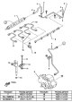
Fuel accumulator
Note: To avoid fuel leaks, do not remove the fuel pressure sensor and pressure relief valve. When removing and installing the fuel accumulator, follow the assembly...
Note: To avoid fuel leaks, do not remove the fuel pressure sensor and pressure relief valve. When removing and installing the fuel accumulator, follow the assembly...

Injectors — removal and installation
Attention: Cover all adjacent parts with rags to prevent fuel from spilling on them. After removing the high-pressure fuel pipes, do not allow dirt or foreign materials...
Attention: Cover all adjacent parts with rags to prevent fuel from spilling on them. After removing the high-pressure fuel pipes, do not allow dirt or foreign materials...

Crankshaft position sensor
Removal and installation Caution: When installing the crankshaft position sensor, make sure that it is thoroughly cleaned of any foreign metal materials, otherwise the...
Removal and installation Caution: When installing the crankshaft position sensor, make sure that it is thoroughly cleaned of any foreign metal materials, otherwise the...

Camshaft Position Sensor
Removal and installation Attention: When installing the camshaft position sensor, make sure that it is thoroughly cleaned of any foreign metal materials, otherwise the...
Removal and installation Attention: When installing the camshaft position sensor, make sure that it is thoroughly cleaned of any foreign metal materials, otherwise the...

Fuel filter water presence sensor
1. Disconnect the cable from the negative terminal of the battery. 2. Follow the procedures in the section " Before carrying out repair work ". 3. Drain the fuel from...
1. Disconnect the cable from the negative terminal of the battery. 2. Follow the procedures in the section " Before carrying out repair work ". 3. Drain the fuel from...

Mass Air Flow Sensor / Intake Air Temperature Sensor #2
Checking the mass air flow sensor 1. Turn the ignition key to the "ON" position (the engine is turned off). 2. Connect the scanner to the diagnostic connector and check...
Checking the mass air flow sensor 1. Turn the ignition key to the "ON" position (the engine is turned off). 2. Connect the scanner to the diagnostic connector and check...

Intake Air Temperature Sensor #1 / Boost Pressure Sensor
Checking the intake air temperature sensor #1 1. Disconnect the cable from the negative terminal of the battery. 2. Remove the sensor. 3. Using an ohmmeter, measure the...
Checking the intake air temperature sensor #1 1. Disconnect the cable from the negative terminal of the battery. 2. Remove the sensor. 3. Using an ohmmeter, measure the...
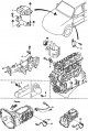
Location of sensors and relays
Location of sensors and relays. 1 - engine control unit, 2 - glow plug relay, 3 - main relay, 4 - sensor No.1 air temperature at the intake / boost pressure sensor, 5 -...
Location of sensors and relays. 1 - engine control unit, 2 - glow plug relay, 3 - main relay, 4 - sensor No.1 air temperature at the intake / boost pressure sensor, 5 -...

Coolant temperature sensor
Caution: Make sure the engine is cool before performing the procedure. 1. Disconnect the cable from the negative terminal of the battery. 2. Drain the coolant (see...
Caution: Make sure the engine is cool before performing the procedure. 1. Disconnect the cable from the negative terminal of the battery. 2. Drain the coolant (see...

Accelerator pedal
Removal and installation 1. Disconnect the cable from the negative terminal of the battery. 2. Remove the brake booster and hang it aside without disconnecting the...
Removal and installation 1. Disconnect the cable from the negative terminal of the battery. 2. Remove the brake booster and hang it aside without disconnecting the...

Accelerator pedal position sensor
Examination 1. Check the accelerator pedal for damage and loose parts. 2. Check that the accelerator pedal position sensor is installed correctly. 3. Measure the voltage...
Examination 1. Check the accelerator pedal for damage and loose parts. 2. Check that the accelerator pedal position sensor is installed correctly. 3. Measure the voltage...

Idling switch
1. Disconnect the idle speed switch connector. 2. Using an ohmmeter, check the conductivity between the switch terminals when changing the position of the rod. The rod...
1. Disconnect the idle speed switch connector. 2. Using an ohmmeter, check the conductivity between the switch terminals when changing the position of the rod. The rod...

Start inhibit switch
Examination 1. Remove the start inhibit switch. 2. Using an ohmmeter, check the conductivity of the switch. a) Make sure there is conductivity between the terminals when...
Examination 1. Remove the start inhibit switch. 2. Using an ohmmeter, check the conductivity of the switch. a) Make sure there is conductivity between the terminals when...

Main relay
1. Disconnect the cable from the negative terminal of the battery. 2. Remove the main relay. 3. Using an ohmmeter, check the conductivity of the relay. a) Make sure...
1. Disconnect the cable from the negative terminal of the battery. 2. Remove the main relay. 3. Using an ohmmeter, check the conductivity of the relay. a) Make sure...

Clutch pedal switch
Examination 1. Disconnect the switch connector. 2. Using an ohmmeter, check the conductivity between the switch terminals by pressing and releasing the rod. The rod is...
Examination 1. Disconnect the switch connector. 2. Using an ohmmeter, check the conductivity between the switch terminals by pressing and releasing the rod. The rod is...

Removal and installation of exhaust gas recirculation system components
1. Disconnect the cable from the negative terminal of the battery. 2. Remove the parts in the sequence shown in the figure below. Location of emission control system...
1. Disconnect the cable from the negative terminal of the battery. 2. Remove the parts in the sequence shown in the figure below. Location of emission control system...

Exhaust Gas Recirculation System Checks
Checking the EGR valve position sensor 1. Disconnect the sensor connector. 2. Using an ohmmeter, measure the resistance between terminals "A" and "B" of the sensor....
Checking the EGR valve position sensor 1. Disconnect the sensor connector. 2. Using an ohmmeter, measure the resistance between terminals "A" and "B" of the sensor....

Fuel tank
Removal and installation Warning: Repairing a fuel tank that has not been properly steam cleaned can be dangerous. A tank explosion or fire can cause serious injury or...
Removal and installation Warning: Repairing a fuel tank that has not been properly steam cleaned can be dangerous. A tank explosion or fire can cause serious injury or...

Engine control unit
Removal and installation 1. Disconnect the cable from the negative terminal of the battery. 2. Remove the front side trim. 3. Remove the parts in the order they are...
Removal and installation 1. Disconnect the cable from the negative terminal of the battery. 2. Remove the front side trim. 3. Remove the parts in the order they are...

Diagnostic system
Description The electronic engine control unit has a built-in self-diagnostic system, which continuously monitors the engine condition using sensor signals. The...
Description The electronic engine control unit has a built-in self-diagnostic system, which continuously monitors the engine condition using sensor signals. The...
This section is available on: russian, bulgarian, belarusian, ukrainian, serbian, croatian, romanian, polish, slovak, hungarian
More sections on repairs of other Mazda models
• Power unit: Injection system Mazda Familia 6 (1989-1994)
• Power unit: Fuel injection (FE) Mazda Capella 4 (1987-1992)
• Power unit: Injection system Mazda Familia 6 (1989-1994)
• Power unit: Fuel injection (FE) Mazda Capella 4 (1987-1992)
Link in different formats to this section
TEXTHTMLBB Code
- General information
- Introduction to guide
- User manual
- Maintenance
- Power unit
- Engine repair (diesel)
- Cooling and lubrication system
- Fuel injection system
- Intake and exhaust system
- Engine electrical equipment
- Transmission
- Clutch
- Mechanical gearbox
- All-wheel drive system
- Transfer case and gearboxes
- Chassis
- Front suspension
- Rear suspension
- Steering
- Brake system
- Body
- Exterior (external elements)
- Interior (internal elements)
- Heating and air conditioning
- Security system SRS
- Electrical equipment
- Equipment and devices
- Electrical circuits
- General information
- User manual
- Maintenance
- Power unit
- Petrol engine 1.3 l
- Petrol engine 1.25/1.4 l
- Diesel engine
- Lubrication system
- Cooling system
- Ignition system
- Supply system
- Fuel injection (gasoline)
- Fuel injection (diesel)
- Exhaust system
- Transmission
- Clutch
- Car gearbox
- Chassis
- Front suspension
- Rear suspension
- Steering
- Brake system
- Wheels and tires
- Body
- Exterior (external elements)
- Interior (internal elements)
- Doors, windows and locks
- Heating system
- Electrical equipment
- Troubleshooting
- Equipment and devices
- Lighting system
- Power devices
- Electrical circuits