


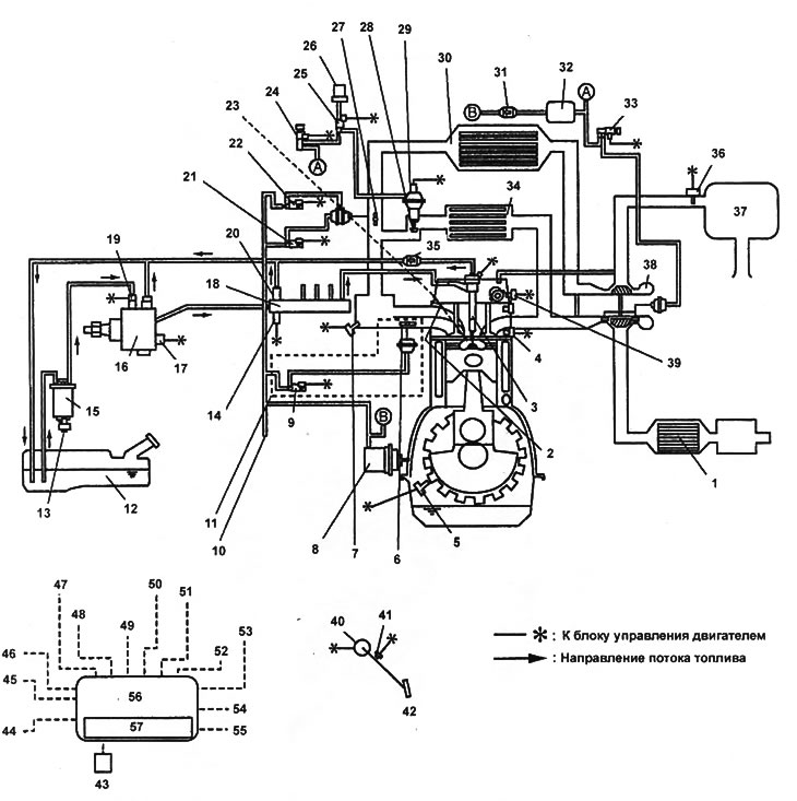
Diagram of the fuel system, air intake system and exhaust system.
1 - oxidizing neutralizer,
2 - glow plug,
3 - nozzle,
4 - coolant temperature sensor,
5 - crankshaft position sensor,
6 - variable intake air flow control (VSC) drive,
7 - boost pressure sensor/intake air temperature sensor No.1,
8 - vacuum pump,
9 - electromagnetic valve of the variable air flow system (VSC),
10 - to the brake booster,
11 - models with VSC system,
12 - fuel tank,
13 - sensor for the presence of water in the fuel filter,
14 - fuel accumulator pressure sensor,
15 - fuel filter,
16 - Fuel injection pump,
17 - fuel pressure control valve,
18 - fuel accumulator,
19 - fuel temperature sensor,
20 - pressure reducing valve,
21 - electromagnetic valve No.2 for throttle control,
22 - electromagnetic valve No.1 of throttle control,
23 - to the glow plug relay,
24 - electromagnetic valve of the exhaust gas recirculation system,
25 - electromagnetic control valve of the exhaust gas recirculation system,
26 - air filter,
27 - VIS system valve,
28 - EGR valve,
29 - EGR valve position sensor,
30 - charge air cooler,
31 - vacuum control valve,
32 - vacuum receiver,
33 - electromagnetic valve for controlling boost pressure,
34 - EGR cooler,
35 - control valve,
36 - mass air flow sensor/intake air temperature sensor No.2,
37 - air filter,
38 - turbocharger,
39 - camshaft position sensor,
40 - accelerator pedal position sensor,
41 - idle switch,
42 - accelerator pedal,
43 - glow plug relay,
44 - indicator "Check Engine",
45 - "GLOW" indicator,
46 - tachometer,
47 - main relay,
48 - ignition switch,
49 - start inhibit switch,
50 - air conditioner switch,
51 - diagnostic connector No.2 (terminal "TEN"),
52 - vehicle speed signal,
53 - CAN data bus,
54 - clutch pedal switch,
55 - air conditioner relay,
56 - engine control unit,
57 - atmospheric pressure sensor.
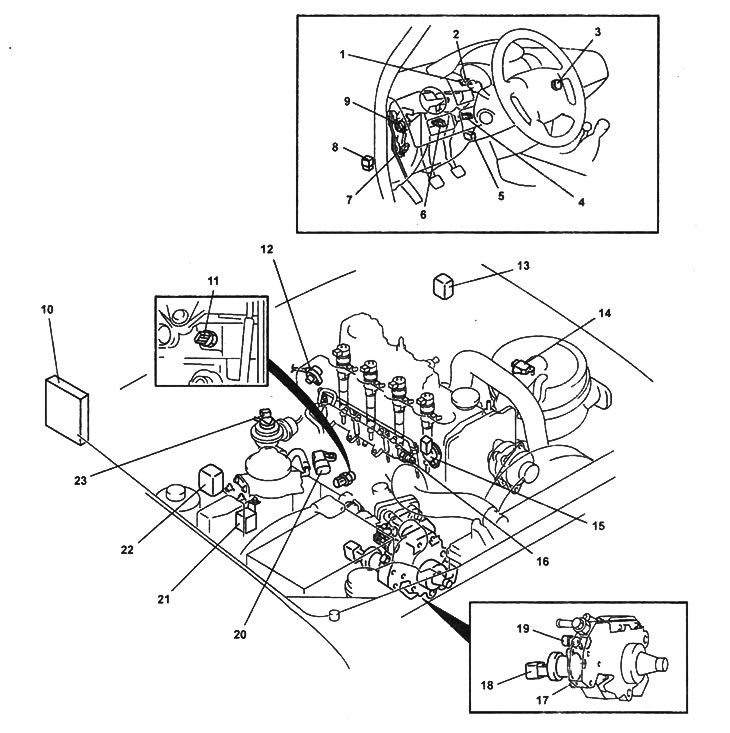
Location of components of the electronic engine control system.
1 - "GLOW" indicator,
2 - indicator "Check Engine",
3 - air conditioner switch,
4 - clutch pedal switch,
5 - diagnostic connector No.2,
6 - brake light switch,
7 - idle switch,
8 - main relay,
9 - accelerator pedal position sensor,
10 - engine control unit with built-in atmospheric pressure sensor,
11 - coolant temperature sensor,
12 - crankshaft position sensor,
13 - diagnostic connector,
14 - mass air flow sensor/intake air temperature sensor No.2,
15 - camshaft position sensor,
16 - fuel pressure sensor in the fuel accumulator,
17 - Fuel injection pump,
18 - fuel pressure control valve,
19 - fuel temperature sensor,
20 - boost pressure sensor/intake air temperature sensor No.1,
21 - glow plug relay,
22 - air conditioner relay,
23 - EGR valve position sensor.