


Vehicle wiring diagrams Mazda 121 (3)

Conventional symbols for electrical circuits
A11 - radio receiver A30 - instrument cluster A30 (7) - left turn signal indicator lamp A30 (8) - right turn signal indicator lamp A30 (15) - tachometer A30 (21) -...
A11 - radio receiver A30 - instrument cluster A30 (7) - left turn signal indicator lamp A30 (8) - right turn signal indicator lamp A30 (15) - tachometer A30 (21) -...

Diagram 1. Endura-E engine
Diagram 1. Endura-E engine Conventional symbols for electrical circuits are located here →
Diagram 1. Endura-E engine Conventional symbols for electrical circuits are located here →

Diagram 2. Endura-E (I) Engine Management System
Diagram 2. Endura-E (I) Engine Management System Conventional symbols for electrical circuits are located here →
Diagram 2. Endura-E (I) Engine Management System Conventional symbols for electrical circuits are located here →
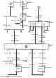
Diagram 3. Engine management system Endura-E (II)
Diagram 3. Engine management system Endura-E (II) Conventional symbols for electrical circuits are located here →
Diagram 3. Engine management system Endura-E (II) Conventional symbols for electrical circuits are located here →
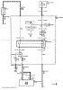
Diagram 4. Zetec-SE engine (I)
Diagram 4. Zetec-SE engine (I) Conventional symbols for electrical circuits are located here →
Diagram 4. Zetec-SE engine (I) Conventional symbols for electrical circuits are located here →
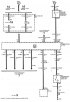
Scheme 5. Fuel supply of the Zetec-SE (II) engine
Scheme 5. Fuel supply of the Zetec-SE (II) engine Conventional symbols for electrical circuits are located here →
Scheme 5. Fuel supply of the Zetec-SE (II) engine Conventional symbols for electrical circuits are located here →
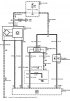
Scheme 6. Engine management system Zetec-SE (I)
Scheme 6. Engine management system Zetec-SE (I) Conventional symbols for electrical circuits are located here →
Scheme 6. Engine management system Zetec-SE (I) Conventional symbols for electrical circuits are located here →

Scheme 7. Engine management system Zetec-SE (II)
Scheme 7. Engine management system Zetec-SE (II) Conventional symbols for electrical circuits are located here →
Scheme 7. Engine management system Zetec-SE (II) Conventional symbols for electrical circuits are located here →
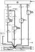
Scheme 3. Engine management system Zetec-SE (with automatic transmission STX)
Scheme 3. Zetec-SE engine management system (with automatic transmission STX) Conventional symbols for electrical circuits are located here →
Scheme 3. Zetec-SE engine management system (with automatic transmission STX) Conventional symbols for electrical circuits are located here →
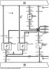
Diagram 9. Engine management system Endura-DE (I)
Diagram 9. Engine management system Endura-DE (I) Conventional symbols for electrical circuits are located here →
Diagram 9. Engine management system Endura-DE (I) Conventional symbols for electrical circuits are located here →

Diagram 10. Endura-CE (II) Engine Management System
Diagram 10. Endura-CE (II) Engine Management System Conventional symbols for electrical circuits are located here →
Diagram 10. Endura-CE (II) Engine Management System Conventional symbols for electrical circuits are located here →

Diagram 11. Endura-CE engine preheating system
Diagram 11. Endura-CE engine preheating system Conventional symbols for electrical circuits are located here →
Diagram 11. Endura-CE engine preheating system Conventional symbols for electrical circuits are located here →

Scheme 12. Engine starting system for cars with manual transmission
Scheme 12. Engine starting system for cars with manual transmission Conventional symbols for electrical circuits are located here →
Scheme 12. Engine starting system for cars with manual transmission Conventional symbols for electrical circuits are located here →
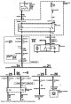
Diagram 13. Radiator fan (Endura-CE without air conditioning)
Scheme 13. Radiator fan (Endura-CE without air conditioning) Conventional symbols for electrical circuits are located here →
Scheme 13. Radiator fan (Endura-CE without air conditioning) Conventional symbols for electrical circuits are located here →

Diagram 14. Radiator fan (Endura-E without air conditioning)
Scheme 14. Radiator fan (Endura-E without air conditioning) Conventional symbols for electrical circuits are located here →
Scheme 14. Radiator fan (Endura-E without air conditioning) Conventional symbols for electrical circuits are located here →
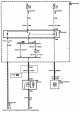
Scheme 15. Radiator fan (Zetec-SE without air conditioning)
Scheme 15. Radiator fan (Zetec-SE without air conditioning) Conventional symbols for electrical circuits are located here →
Scheme 15. Radiator fan (Zetec-SE without air conditioning) Conventional symbols for electrical circuits are located here →

Scheme 16. Headlights with beam corrector
Scheme 16. Headlights with beam corrector Conventional symbols for electrical circuits are located here →
Scheme 16. Headlights with beam corrector Conventional symbols for electrical circuits are located here →
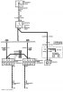
Scheme 17. Brake lights
Scheme 17. Brake lights Conventional symbols for electrical circuits are located here →
Scheme 17. Brake lights Conventional symbols for electrical circuits are located here →
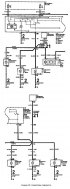
Scheme 18. Direction indicators
Scheme 18. Direction indicators Conventional symbols for electrical circuits are located here →
Scheme 18. Direction indicators Conventional symbols for electrical circuits are located here →
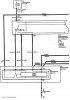
Scheme 19. Sound signal
Scheme 19. Sound signal Conventional symbols for electrical circuits are located here →
Scheme 19. Sound signal Conventional symbols for electrical circuits are located here →

Scheme 20. Windshield wiper and washer
Scheme 20. Windshield wiper and washer Conventional symbols for electrical circuits are located here →
Scheme 20. Windshield wiper and washer Conventional symbols for electrical circuits are located here →
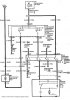
Scheme 21. Rear window wiper and washer
Scheme 21. Rear window wiper and washer Conventional symbols for electrical circuits are located here →
Scheme 21. Rear window wiper and washer Conventional symbols for electrical circuits are located here →
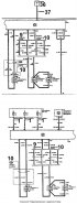
Diagram 22. Radio / audio system
Diagram 22. Radio / audio system Conventional symbols for electrical circuits are located here →
Diagram 22. Radio / audio system Conventional symbols for electrical circuits are located here →
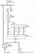
Heating and ventilation system (2000-2001)
Heating and ventilation system (2000-2001 years of release)
Heating and ventilation system (2000-2001 years of release)
This section is available on: russian, bulgarian, belarusian, ukrainian, serbian, croatian, romanian, polish, slovak, hungarian
More sections on repairs of other Mazda models
• Electrical equipment: Electrical circuits Mazda Familia 5 (1985-1989)
• Electrical equipment: Electrical circuits Mazda Capella 6 (1997-2005, petrol)
• Electrical equipment: Electrical circuits Mazda CX-5KE (2012-2017)
• Electrical equipment: Electrical circuits Mazda Familia 5 (1985-1989)
• Electrical equipment: Electrical circuits Mazda Capella 6 (1997-2005, petrol)
• Electrical equipment: Electrical circuits Mazda CX-5KE (2012-2017)
Link in different formats to this section
TEXTHTMLBB Code
- General information
- Introduction to guide
- User manual
- Maintenance
- Power unit
- Engine repair (diesel)
- Cooling and lubrication system
- Fuel injection system
- Intake and exhaust system
- Engine electrical equipment
- Transmission
- Clutch
- Mechanical gearbox
- All-wheel drive system
- Transfer case and gearboxes
- Chassis
- Front suspension
- Rear suspension
- Steering
- Brake system
- Body
- Exterior (external elements)
- Interior (internal elements)
- Heating and air conditioning
- Security system SRS
- Electrical equipment
- Equipment and devices
- Electrical circuits
- General information
- User manual
- Maintenance
- Power unit
- Petrol engine 1.3 l
- Petrol engine 1.25/1.4 l
- Diesel engine
- Lubrication system
- Cooling system
- Ignition system
- Supply system
- Fuel injection (gasoline)
- Fuel injection (diesel)
- Exhaust system
- Transmission
- Clutch
- Car gearbox
- Chassis
- Front suspension
- Rear suspension
- Steering
- Brake system
- Wheels and tires
- Body
- Exterior (external elements)
- Interior (internal elements)
- Doors, windows and locks
- Heating system
- Electrical equipment
- Troubleshooting
- Equipment and devices
- Lighting system
- Power devices
- Electrical circuits