


Vehicle equipment and instruments Mazda BT-50 1

Body electrical equipment — fuses
Caution: Determine and correct the cause of the blown fuse before replacing it. Replacing the fuse before correcting the problem may cause the fuse to blow again....
Caution: Determine and correct the cause of the blown fuse before replacing it. Replacing the fuse before correcting the problem may cause the fuse to blow again....

Combination Switch — Disassembly and Assembly
Disassemble the combination switch, referring to the assembly drawing "Disassembling and assembling the combination switch". Disassembling and assembling the combination...
Disassemble the combination switch, referring to the assembly drawing "Disassembling and assembling the combination switch". Disassembling and assembling the combination...

Lighting system — device
Location of external lighting system components. 1 - headlight, 2 - turn signal repeater, 3 - license plate light bulbs, 4 - rear combination light, 5 - additional brake...
Location of external lighting system components. 1 - headlight, 2 - turn signal repeater, 3 - license plate light bulbs, 4 - rear combination light, 5 - additional brake...

Lighting system — headlight
The headlight assembly includes a low beam and high beam lamp, a parking light lamp and a turn signal lamp (see the "Headlight Assembly" figure). Headlight unit....
The headlight assembly includes a low beam and high beam lamp, a parking light lamp and a turn signal lamp (see the "Headlight Assembly" figure). Headlight unit....
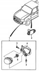
Disassembly and assembly of turn signal repeater and fog lamp
Disassemble the turn signal repeater and fog lamp, following the assembly drawing "Disassembling and assembling the turn signal repeater and fog lamp". Disassembly and...
Disassemble the turn signal repeater and fog lamp, following the assembly drawing "Disassembling and assembling the turn signal repeater and fog lamp". Disassembly and...
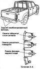
Rear combination light
The rear combination light includes a brake light/side light, a direction indicator light and a reversing light (see the illustration "Rear combination light"). Rear...
The rear combination light includes a brake light/side light, a direction indicator light and a reversing light (see the illustration "Rear combination light"). Rear...
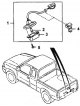
Disassembling and assembling the license plate light
Disassemble the license plate light bulb using the assembly drawing "Disassembling and assembling the license plate light bulb". Disassembling and assembling the license...
Disassemble the license plate light bulb using the assembly drawing "Disassembling and assembling the license plate light bulb". Disassembling and assembling the license...
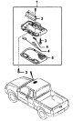
Disassembling and assembling the interior lighting lamp / local lighting
Disassemble the interior/local lighting lamp, referring to the assembly drawing "Disassembling and assembling the interior/local lighting lamp". Disassembly and assembly...
Disassemble the interior/local lighting lamp, referring to the assembly drawing "Disassembling and assembling the interior/local lighting lamp". Disassembly and assembly...


Windscreen wipers and washers
Removal and installation the windshield wiper Remove the windshield wiper, referring to the assembly drawing "Removing and installing the windshield wiper". Removal and...
Removal and installation the windshield wiper Remove the windshield wiper, referring to the assembly drawing "Removing and installing the windshield wiper". Removal and...

Instrument cluster — disassembly and assembly
Disassemble the instrument cluster using the assembly drawing "Disassembling and assembling the instrument cluster". Disassembly and assembly of the instrument cluster....
Disassemble the instrument cluster using the assembly drawing "Disassembling and assembling the instrument cluster". Disassembly and assembly of the instrument cluster....

Instrument cluster — device
Instrument cluster (gauges). 1 - tachometer, 2 - speedometer, 3 - coolant temperature indicator, 4 - fuel level indicator, 5 - mileage counter switch, 6 - odometer /...
Instrument cluster (gauges). 1 - tachometer, 2 - speedometer, 3 - coolant temperature indicator, 4 - fuel level indicator, 5 - mileage counter switch, 6 - odometer /...

Immobilizer components
Key The key contains a transmitter with a recorded code (ID). Ring antenna The ring antenna is located in the steering column lock, it receives the key code (ID) and...
Key The key contains a transmitter with a recorded code (ID). Ring antenna The ring antenna is located in the steering column lock, it receives the key code (ID) and...

Immobilizer diagnostics
1. Turn the ignition switch to the "ON" position. 2. Make sure the immobilizer system indicator is working properly. 3. Read the fault codes from the immobilizer system...
1. Turn the ignition switch to the "ON" position. 2. Make sure the immobilizer system indicator is working properly. 3. Read the fault codes from the immobilizer system...
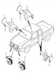
Sound signal and door limit switches
Removal and installation Remove the horn and door limit switches, referring to the assembly drawing "Removing and installing the horn and door limit switches". Removal...
Removal and installation Remove the horn and door limit switches, referring to the assembly drawing "Removing and installing the horn and door limit switches". Removal...

Electric windows
Note: When disconnecting the negative battery cable, replacing the "PAVIND" fuse, or disconnecting the connectors from the power window switches, perform the following...
Note: When disconnecting the negative battery cable, replacing the "PAVIND" fuse, or disconnecting the connectors from the power window switches, perform the following...

Removal and installation the main window control switch
1. Disconnect the cable from the negative terminal of the battery. 2. Press the "C" latch with a flat-head screwdriver wrapped in electrical tape. 3. Disconnect the...
1. Disconnect the cable from the negative terminal of the battery. 2. Press the "C" latch with a flat-head screwdriver wrapped in electrical tape. 3. Disconnect the...

Checking the main power window control switch
Checking the chain 1. Check the voltage at the terminals of the main switch according to the table "Checking the main window control switch". Table: Checking the main...
Checking the chain 1. Check the voltage at the terminals of the main switch according to the table "Checking the main window control switch". Table: Checking the main...

Removal and installation window lifter control switches
1. Disconnect the cable from the negative terminal of the battery. 2. Press the "C" latch with a flat-head screwdriver wrapped in electrical tape. 3. Disconnect the...
1. Disconnect the cable from the negative terminal of the battery. 2. Press the "C" latch with a flat-head screwdriver wrapped in electrical tape. 3. Disconnect the...

Checking the window control switch
1. Remove the front passenger door, left rear door or right rear door power window control switch. 2. Check the conductivity at the switch terminals using an ohmmeter....
1. Remove the front passenger door, left rear door or right rear door power window control switch. 2. Check the conductivity at the switch terminals using an ohmmeter....

Removal and installation electric window lifters
Front doors 1. Disconnect the cable from the negative terminal of the battery. 2. Remove the interior trim. 3. Remove the door trim panel. 4. Remove the cover of the...
Front doors 1. Disconnect the cable from the negative terminal of the battery. 2. Remove the interior trim. 3. Remove the door trim panel. 4. Remove the cover of the...

Checking the window lifter motor
Check the operation of the window lift by applying battery voltage to terminals "2A" and "2B". Attention: if the electric motor is very hot, the thermal fuse may operate...
Check the operation of the window lift by applying battery voltage to terminals "2A" and "2B". Attention: if the electric motor is very hot, the thermal fuse may operate...

External mirror adjustment system
For the location of the exterior mirror components, see the illustration "Location of glass, power windows and rear view mirror components". Checking the electric drive...
For the location of the exterior mirror components, see the illustration "Location of glass, power windows and rear view mirror components". Checking the electric drive...

Rear window defroster
Checking heater wires 1. Turn the ignition switch to the "ON" position. 2. Turn on the rear window defroster. Caution: When measuring voltage, wrap the end of the...
Checking heater wires 1. Turn the ignition switch to the "ON" position. 2. Turn on the rear window defroster. Caution: When measuring voltage, wrap the end of the...

Central locking and anti-theft system
Anti-theft system modes Not active (Dead) The ignition key is in the "ON", "ACC" or "LOCK" position. The anti-theft system indicator does not light. Initial setup The...
Anti-theft system modes Not active (Dead) The ignition key is in the "ON", "ACC" or "LOCK" position. The anti-theft system indicator does not light. Initial setup The...

Central lock components — device
Location of components of the central locking and anti-theft system. 1 - hood opening sensor, 2 - central lock control unit, 3 - anti-theft system control unit, 4 -...
Location of components of the central locking and anti-theft system. 1 - hood opening sensor, 2 - central lock control unit, 3 - anti-theft system control unit, 4 -...

Location of audio system components
Location of audio system components. 1 - right high frequency speaker, 2 - antenna on the roof, 3 - front right speaker, 4 - left high frequency speaker, 5 - rear right...
Location of audio system components. 1 - right high frequency speaker, 2 - antenna on the roof, 3 - front right speaker, 4 - left high frequency speaker, 5 - rear right...

Audio system — disassembling and assembling the radio
Disassemble the radio, following the assembly drawing "Disassembling and assembling the radio". Table. Radio connector pins. Disassembling and assembling the radio. 1 -...
Disassemble the radio, following the assembly drawing "Disassembling and assembling the radio". Table. Radio connector pins. Disassembling and assembling the radio. 1 -...

Radio diagnostics
1. Reading codes. a) Turn the ignition switch to the "ACC" or "ON" position. b) Press the "POWER" key, then press the "FM 1" and "MEDIA" keys simultaneously for 2...
1. Reading codes. a) Turn the ignition switch to the "ACC" or "ON" position. b) Press the "POWER" key, then press the "FM 1" and "MEDIA" keys simultaneously for 2...
This section is available on: russian, bulgarian, belarusian, ukrainian, serbian, croatian, romanian, polish, slovak, hungarian
More sections on repairs of other Mazda models
• Electrical equipment: Equipment and devices Mazda Familia 6 (1989-1994)
• Electrical equipment: Equipment and devices Mazda Capella 3 and 4 (1982-1992)
• Electrical equipment: Equipment and devices Mazda3 BK (2003-2009)
• Electrical equipment: Equipment and devices Mazda6 GG (2002-2008)
• Electrical equipment: Equipment and devices Mazda CX-5KE (2012-2017)
• Electrical equipment: Equipment and devices Mazda Familia 6 (1989-1994)
• Electrical equipment: Equipment and devices Mazda Capella 3 and 4 (1982-1992)
• Electrical equipment: Equipment and devices Mazda3 BK (2003-2009)
• Electrical equipment: Equipment and devices Mazda6 GG (2002-2008)
• Electrical equipment: Equipment and devices Mazda CX-5KE (2012-2017)
Link in different formats to this section
TEXTHTMLBB Code
- General information
- Introduction to guide
- User manual
- Maintenance
- Power unit
- Engine repair (diesel)
- Cooling and lubrication system
- Fuel injection system
- Intake and exhaust system
- Engine electrical equipment
- Transmission
- Clutch
- Mechanical gearbox
- All-wheel drive system
- Transfer case and gearboxes
- Chassis
- Front suspension
- Rear suspension
- Steering
- Brake system
- Body
- Exterior (external elements)
- Interior (internal elements)
- Heating and air conditioning
- Security system SRS
- Electrical equipment
- Equipment and devices
- Electrical circuits
- General information
- User manual
- Maintenance
- Power unit
- Petrol engine 1.3 l
- Petrol engine 1.25/1.4 l
- Diesel engine
- Lubrication system
- Cooling system
- Ignition system
- Supply system
- Fuel injection (gasoline)
- Fuel injection (diesel)
- Exhaust system
- Transmission
- Clutch
- Car gearbox
- Chassis
- Front suspension
- Rear suspension
- Steering
- Brake system
- Wheels and tires
- Body
- Exterior (external elements)
- Interior (internal elements)
- Doors, windows and locks
- Heating system
- Electrical equipment
- Troubleshooting
- Equipment and devices
- Lighting system
- Power devices
- Electrical circuits