
MazBook.ru
English Русский
Български
Беларускі
Український
Српски
Hrvatski
Română
Polski
Slovenský
Magyar
• Bookmark • Sitemap • Contacts •   
Cars Opel Cars Ford Cars Volkswagen Cars Audi Cars Kia Cars Renault Cars Peugeot


Familia Capella Mazda3 Mazda6 CX-? Others Articles
Mazda 121 (3) (1996-2003) Mazda BT-50 (1) (2006-2011)

Accelerator pedal (Mazda BT-50 (1))

  • Home
  • Mazda
  • BT-50 J97M (2006-2011)
  • Power unit
  • Fuel injection system
  • Accelerator pedal
0
Contents: Removal and installation ⇓ Disassembly and assembly ⇓ Adjusting the accelerator pedal…⇓

Removal and installation


1. Disconnect the cable from the negative terminal of the battery.

2. Remove the brake booster and hang it aside without disconnecting the hoses.

3. Remove the clutch release slave cylinder and hang it to the side without disconnecting the hoses.

4. Remove the steering column cover and steering shaft.

5. Remove the parts in the order they are numbered in the figure.
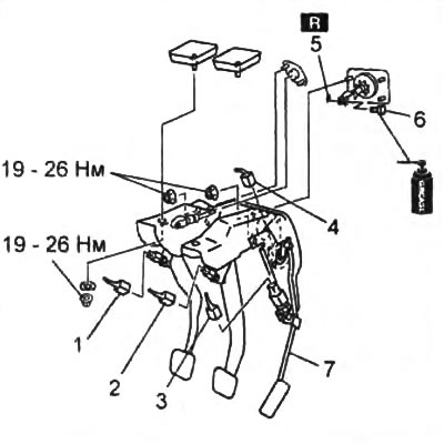
1 - start inhibit switch connector,

1 - start inhibit switch connector,
2 - brake light switch connector,
3 - idle speed switch connector,
4 - accelerator pedal position sensor connector,
5 - cotter pin,
6 - pin,
7 - pedals assembled.


6. Check the accelerator pedal for damage and loose parts.

If necessary, replace the accelerator pedal.

7. When assembling, the parts are installed in the reverse order.

8. After installation, check and adjust the clutch and brake pedals.

Disassembly and assembly


Remove the parts as shown in the figure.
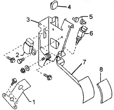
1 - limiter,

1 - limiter,
2 - accelerator pedal position sensor,
3 - accelerator pedal bracket,
4 - spacer,
5 - rubber stopper,
6 - idle switch,
7 - accelerator pedal,
8 - overlay.


Adjusting the accelerator pedal position sensor and idle switch


Caution: Adjusting the accelerator pedal position sensor and idle switch may adversely affect the operation of the engine management system. Adjust these components only when replacing them.


1. Install the accelerator pedal position sensor and idle switch to the pedal. Lightly tighten the pedal position sensor mounting bolts and the idle switch lock nut.

2. Connect the connectors to the accelerator pedal position sensor and idle speed switch.

3. Set the ignition switch to the "OM" position (engine off).

4. Measure the voltage between terminals "A" and "D" of the sensor.
  • Voltage - 4.9 - 5.1 V (nominal value 5.0 V)
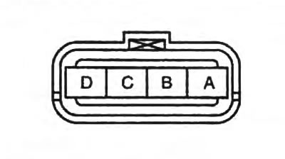
Voltage - 4.9 - 5.1 V (nominal value 5.0 V)


5. Connect the scanner to the diagnostic connector and, using the scanner, check the readings of accelerator pedal position sensors No.1 and No.2 (APP and APP2).

6. Adjust the position of the sensor so that when the accelerator pedal is fully released, the readings of both sensors correspond to the nominal values.
  • Voltage - 0.5 - 0.7 V (nominal value 0.6 V)

7. Tighten the accelerator pedal position sensor mounting bolts.
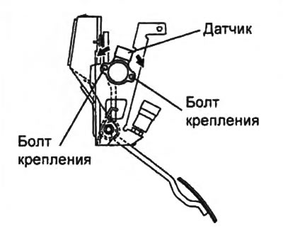
7. Tighten the accelerator pedal position sensor mounting bolts.


8. Press the accelerator pedal with your hand until the accelerator pedal touches the rubber stopper as shown in the figure. Adjust the stopper position so that when the pedal touches it, the voltage of the pedal position sensor signals corresponds to the nominal value.


  • Voltage - 3.4 - 3.8 V (nominal value 3.6 V)
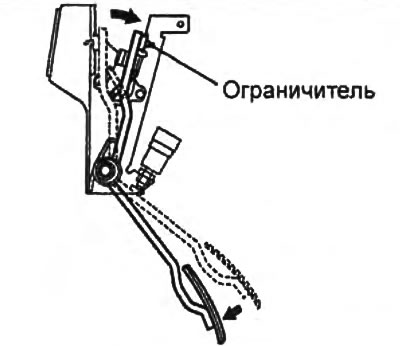
Voltage - 3.4 - 3.8 V (nominal value 3.6 V)


9. Select the Idle Speed Switch option on the scanner (IVS).

10. Gradually depress the accelerator pedal to adjust the idle speed switch position so that the IVS reading changes from "ON" to "OFF" with the APP and APP2 sensor signal voltage corresponding to the specified value.
  • Voltage - 1.0 - 1.2 V (nominal value 1.1 V)
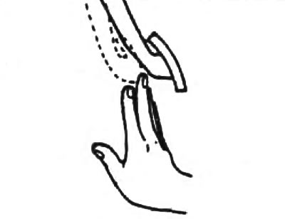
Voltage - 1.0 - 1.2 V (nominal value 1.1 V)


11. Tighten the idle switch lock nut.
  • Tightening torque - 13 - 15 Nm

12. Release the accelerator pedal and check that the IVS display changes from "OFF" to "ON" with the pedal fully released.

13. Press the accelerator pedal again and check that the IVS reading has changed from "ON" to "OFF" with the APP and APP2 sensor signal voltage specified in point "10".
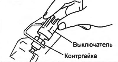
13. Press the accelerator pedal again and check that the IVS reading has changed from «ON» to «OFF»…
This article is available at: russian, bulgarian, belarusian, ukrainian, serbian, croatian, romanian, polish, slovak, hungarian
This text was checked by: Vladimir Bazhenov
Share with friends on social networks:

Previous
Mazda BT-50 (1) » Fuel injection system
Next

Coolant temperature sensor
Location of sensors and relays
Intake Air Temperature Sensor #1 / Boost Pressure Sensor
Mass Air Flow Sensor / Intake Air Temperature Sensor #2
Fuel filter water presence sensor
Accelerator pedal position sensor
Idling switch
Start inhibit switch
Main relay
Clutch pedal switch
More articles on repairing other Mazda models
Accelerator pump Mazda Familia 5 (1985-1989)
Brake pedal Mazda Capella 3 (1982-1992, petrol)
Removal and installation the fuel control pedal (diesel) Mazda3 BK (2003-2009)
Adjusting the height of the pedal position Mazda6 GG (2002-2008)
Accelerator pedal position sensor Mazda CX-5KE (2012-2017)
Link in different formats to this article
Comments and feedback from visitors
No comments yet


How much will 34 + 24 ?


Mazda BT-50 (1) (2006-2011) 
  • General information
  • Introduction to guide
  • User manual
  • Maintenance
  • Power unit
  • Engine repair (diesel)
  • Cooling and lubrication system
  • Fuel injection system
  • Intake and exhaust system
  • Engine electrical equipment
  • Transmission
  • Clutch
  • Mechanical gearbox
  • All-wheel drive system
  • Transfer case and gearboxes
  • Chassis
  • Front suspension
  • Rear suspension
  • Steering
  • Brake system
  • Body
  • Exterior (external elements)
  • Interior (internal elements)
  • Heating and air conditioning
  • Security system SRS
  • Electrical equipment
  • Equipment and devices
  • Electrical circuits
Mazda 121 (3) (1996-2003) 
  • General information
  • User manual
  • Maintenance
  • Power unit
  • Petrol engine 1.3 l
  • Petrol engine 1.25/1.4 l
  • Diesel engine
  • Lubrication system
  • Cooling system
  • Ignition system
  • Supply system
  • Fuel injection (gasoline)
  • Fuel injection (diesel)
  • Exhaust system
  • Transmission
  • Clutch
  • Car gearbox
  • Chassis
  • Front suspension
  • Rear suspension
  • Steering
  • Brake system
  • Wheels and tires
  • Body
  • Exterior (external elements)
  • Interior (internal elements)
  • Doors, windows and locks
  • Heating system
  • Electrical equipment
  • Troubleshooting
  • Equipment and devices
  • Lighting system
  • Power devices
  • Electrical circuits
MazBook.ru © 2018–2026 · Mobile version · Articles and news · Sitemap: EN BG BY UA RS HR RO PL SK HU · Feedback · Site search · Add to bookmarks Familia 5 (BF) · Familia 6 (BG) · Capella 3 (GC) · Capella 3 and 4 (GC) · Capella 4 (GD) · Capella 5 (GE) · Capella 6 (GF) · Mazda3 BK · Mazda6 GG · CX-5KE · Mazda 121 (3) · Mazda BT-50 (1) ·
By continuing to use the site, you agree to the use of cookies 🔐