


Contents: Removal and installation ⇓ Registration of injector…⇓ Erasing the control unit memory ⇓ Setting the correction parameters of…⇓ Clearing the correction parameters…⇓
Removal and installation
1. Disconnect the cable from the negative terminal of the battery.
2. Remove the front side trim.
3. Remove the parts in the order they are numbered in the figure.
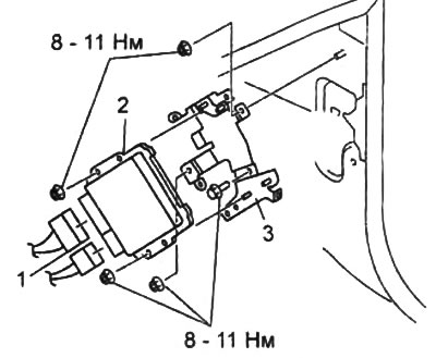
1 - connectors,
2 - engine control unit,
3 - control unit bracket.
4. Installation of parts during assembly is carried out in the reverse order of removal.
5. If the engine control unit was replaced, perform the following procedures:
a) Connect the scanner to the DLC2 diagnostic connector.
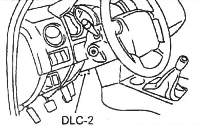
b) In the scanner menu, select "Module Programming", further "Programmable Module Installation", then "PCM" and follow the instructions displayed on the scanner display
c) Perform the immobilizer key programming procedure.
d) Erase the control unit memory (see the relevant subsection below).
d) Perform the procedures described in the section "After performing repair work". Remove air from the fuel system.
e) Start the engine.
g) Set the ignition switch to the "OFF" position.
c) Set the ignition switch to position "0N" (the engine is turned off).
i) Perform diagnostics and check for diagnostic trouble codes that may occur when the engine is off (Key on engine off test).
k) Set the ignition switch to the "OFF" position.
l) Wait 5 seconds,
m) Start the engine,
n) Perform diagnostics and check for diagnostic trouble codes that may occur with the engine running (Key on engine running test),
o) Set the ignition switch to the "OFF" position.
Registration of injector identification codes
Attention:
- After replacing the engine control unit or injectors, it is necessary to program the registration code of the injectors into the control unit memory, otherwise the indicator will light up "Check Engine" and fault codes P1675 and P1676 are displayed.
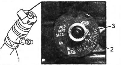
- The injector identification code is applied to the injector body.
Note:
- The injector identification code (2) is an eight-digit digital code applied to the injector body (1). This code contains encrypted injector characteristics (changing depending on the mechanical characteristics of each injector) and is used by the engine control unit to calculate the optimal amount of fuel injected by the injector. Registering this code allows the control unit to optimize the amount of fuel injected by the injector and improve fuel economy.
- There is no need to enter the last two characters of the "AO" code (3) into the control unit memory; these characters indicate that the injector is installed on the WL-C engine.
1. Connect the scanner to the DLC2 diagnostic connector.
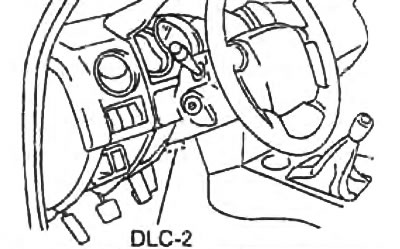
2. In the scanner menu, select "Module programming", further "Programmable parameters", further "injector correction factor" and follow the instructions displayed on the scanner display.
3. Enter the injector identification codes for each cylinder.
After entering the identification codes, check for any diagnostic trouble codes.
Erasing the control unit memory
1. Connect the scanner to the DLC2 diagnostic connector.
2. In the scanner menu, select "Powertrain", further "Data Reset", then "PCM" and follow the instructions displayed on the scanner display.
3. Check for diagnostic trouble codes. Repair if necessary.
Setting the correction parameters of the mass air flow sensor
Caution: This procedure should be performed after replacing the MAF sensor/IAT sensor #2 or every 12 months.
Using a scanner
1. Initial conditions:
a) The engine is warmed up to normal operating temperature.
b) All electrical consumers and air conditioner are turned off.
c) The gear shift lever is in neutral position.
d) The accelerator pedal is fully released.
d) There are no diagnostic trouble codes.
2. Connect the scanner to the DLC2 diagnostic connector.
3. In the scanner menu, select "Powertrain", further "Engine Checks", then "Learning", select "MAF Correction" and follow the instructions displayed on the scanner display.
Without using a scanner
Note: During the procedure, the "GLOW" indicator should be on. After the procedure is completed, the "GLOW" indicator should flash five times.
To perform this procedure without using a scanner, you must short-circuit the "TEN" terminal of the DLC2 diagnostic connector to ground five times within five seconds using a jumper.
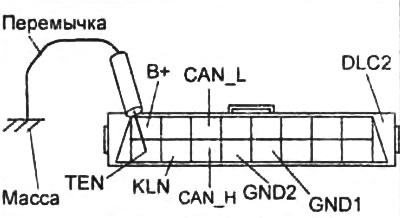
Clearing the correction parameters of the mass air flow sensor
1. Connect the scanner to the DLC2 diagnostic connector.
2. In the scanner menu, select "Powertrain", further "Data Reset", further "MAF Sensor" and follow the instructions displayed on the scanner display.
3. Check for diagnostic trouble codes. Repair if necessary.