Attention:
- Fuel vapors are very dangerous. They are highly flammable and can cause serious injury and damage. There must be no sparking objects or open flames in the area where the fuel is located.
- Fuel spills or fuel leaks from pipes are very dangerous. Fuel can cause skin and eye irritation. Always take precautions when working on the fuel system (see chapter "fuel injection system").
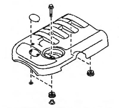
1. Remove the engine trim panel.
2. Disconnect a wire from the negative plug of the storage battery.
3. Drain the coolant (see chapter "Maintenance and general inspection and adjustment procedures").
4. Remove the intake manifold and intake duct (see chapter "Air intake and exhaust system").
5. Remove nozzles (see chapter "fuel injection system").
6. Remove turbocharger (see chapter "Air intake and exhaust system").
7. Remove the timing belt (see section "timing belt").
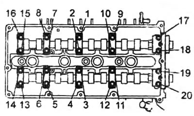
8. Remove the parts in the order they are numbered in the figure "Removal and installation of a head of the block of cylinders".
9. Installation of parts during assembly is carried out in the reverse order of removal.
10. Adjust the tension of the accessory drive belts (see chapter "Maintenance and general inspection and adjustment procedures").
11. Remove air from the fuel system (see chapter "fuel injection system").
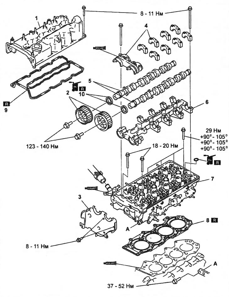
Removal and installation of a head of the block of cylinders.
1 - cylinder head cover,
2 - camshaft pulley,
3 - back cover,
4 - camshaft bearing caps,
5 - camshaft,
6 - bed of camshafts,
7 - cylinder head,
8 - cylinder head gasket,
9 - cylinder head cover gasket (P/N - WE01-10-235),
10 - camshaft oil seal (P/N - WL51-12-602).
12. Check for fuel, engine oil and coolant leaks.
13. Start the engine and check the idle speed (see chapter "Maintenance and general inspection and adjustment procedures").
14. Check the pressure at the end of the compression stroke (see chapter "Maintenance and general inspection and adjustment procedures").
Note on removing camshaft bearing caps
Note: if necessary, mark the covers for subsequent installation in their places. Attention: when removing the camshaft, make sure that no camshaft cam is pressing on the rocker arms, otherwise, when removing, the camshaft may be damaged by the forces of the valve springs.
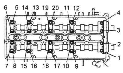
Turn away bolts of fastening of covers of bearings of camshafts in two or three passes in the sequence specified in drawing.
Cylinder head removal note
1. Remove the bolts "A", shown in the figure.
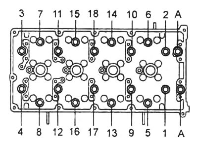
2. Turn away bolts of fastening in two or three passes in the sequence specified in the previous drawing.
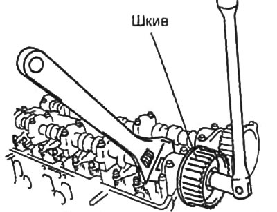
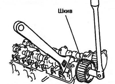
Note on removing the camshaft sprocket
Attention: do not allow the camshaft to turn, otherwise the pistons and valves may be damaged as a result of collision.
Holding the camshaft with a wrench at the hex section, remove the camshaft pulley bolt.
Cylinder Head Gasket Installation Note
1. Using a dial indicator, measure the protrusion of the piston from the cylinder block by setting the piston to TDC.
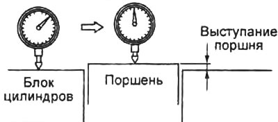
2. Based on the piston protrusion, select a new cylinder head gasket according to the identification mark on the gasket.
Table. Choice of cylinder head gasket.
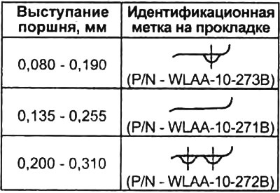 | 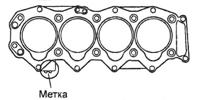 |
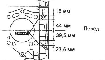
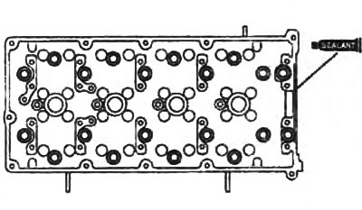
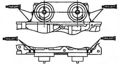
3. Apply a layer of sealant to the cylinder block in the places marked in the figure.
Note: Parts must be installed within the time specified in the instructions for use of the sealant. Otherwise, the sealant must be removed and reapplied.
- Layer thickness - 2.0-3.0 mm
4. Install the cylinder head.
Cylinder head installation note
1. Check the length of each cylinder head bolt. If the maximum value is exceeded, replace the bolt.
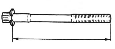
Note: the mounting bolts are marked "W", "N" or "I", check according to them.
Normal length:
- label "W" - 101.2-101.18 mm
- label "N" - 113.2-113.8 mm
- label "I" - 149-150 mm
Maximum length:
- label "W" - 102.5 mm
- label "N" - 114.5 mm
- label "I" - 150.5 mm
2. Apply a coat of engine oil to the threads and under the heads of the cylinder head bolts.
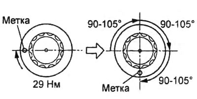
3. Tighten the cylinder head bolts in two or three passes in the sequence shown in the figure.
Note: do not install bolts yet "A".
- Tightening torque - 29 Nm
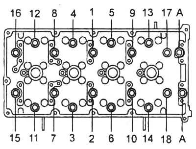
4. Mark the heads of all mounting bolts.
5. Tighten the mounting bolts by 90-105°in the sequence shown in the figure above.
6. Re-tighten the mounting bolts by 90-105°in the sequence shown in the figure above.
7. Once again tighten the mounting bolts by 90-105°in the sequence shown in the figure above.
8. Apply a layer of thread adhesive to the bolt threads "A" fixing the cylinder head.
9. Tighten the bolts "A" (see picture in paragraph "3").
- Tightening torque - 18-20 Nm
Note on installing the camshaft bed
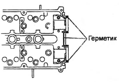
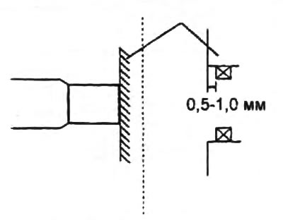
1. Apply a layer of sealant to the cylinder head as shown in the illustration.
Note: Parts must be installed within the time specified in the instructions for use of the sealant. Otherwise, the sealant must be removed and reapplied.
2. Establish a bed of camshafts in a head of the block of cylinders.
Note on installing camshafts
1. Apply a layer of adhesive to the mounting surface of the front camshaft bearing cap.
Note: Parts must be installed within the time specified in the instructions for use of the sealant. Otherwise, the sealant must be removed and reapplied.
2. Establish camshafts and covers of camshafts according to the marks put on them.
3. Tighten bolts of fastening of covers of bearings of camshafts in the sequence specified in drawing.
- Tightening torque - 8-11 Nm
Note: Because the camshaft end play is very small, keep the camshafts level when installing them.
4. Apply a coat of engine oil to the lip of the new camshaft oil seal.
5. Carefully preinstall the oil seal in the cylinder head by hand.
6. Using a hammer and a mandrel of suitable diameter, press in the camshaft oil seal.
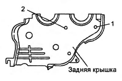
Rear cover installation note
Tighten the rear cover mounting bolts in the sequence shown in the figure.
- Tightening torque - 8 - 11 Nm
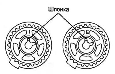
Note on installing camshaft pulleys
1. Install the camshaft pulleys in accordance with the labels applied to them "I - inlet", "E - release", orienting the shaft keys upwards.
2. Holding the camshaft with a wrench by the hex section, tighten the camshaft sprocket bolt.
- Tightening torque - 123-142 Nm
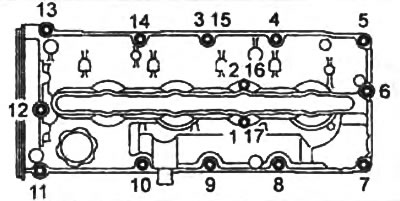
Cylinder Head Cover Installation Note
1. Apply silicone sealant to the contact surfaces of the cylinder head in the places indicated in the figure.
- Layer thickness - 2-3 mm
Note: Parts must be installed within the time specified in the instructions for use of the sealant. Otherwise, the sealant must be removed and reapplied.
2. Tighten bolts of fastening of a cover of a head of the block of cylinders in two stages, in the sequence specified in drawing.
- Tightening torque - 8-11 Nm