
2. Clean the cylinder head.
A) Clear a surface of a head of the block of cylinders of the lining remains.
Note: Be careful not to damage the surface.
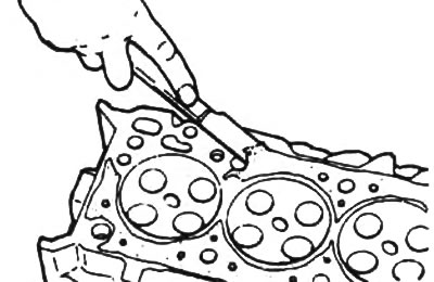
b) Clean the surfaces of the combustion chambers of the cylinder head with a wire brush, removing any remaining carbon deposits.
V) Clean the surface of the cylinder head mating with the surface of the cylinder block using a soft brush and solvent.
3. Using a penetrating dye, check for cracks in the combustion chambers, inlet and outlet ports, and at the gas interface. If there are cracks, replace the cylinder head.
4. Check the fit of the valves. Replace if necessary.
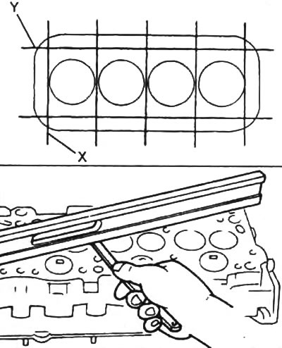
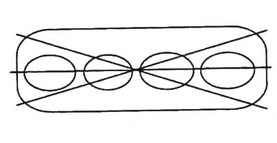
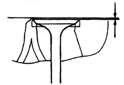
5. Check the cylinder head. With a precision ruler and a flat feeler gauge, as shown in the figure, check the flatness of the working surfaces of the cylinder head mating with the surface of the cylinder block, intake and exhaust manifolds.
Caution: handle the cylinder head carefully, taking care not to damage its bottom surface.
The maximum allowable non-flatness of the surface mating with the surface of the cylinder block:
- towards "X" — 0.02 m/m
- towards "Y" — 0.05 m/m
The maximum allowable flatness of the surface mating with the surfaces of the intake and exhaust manifold is 0.05 mm
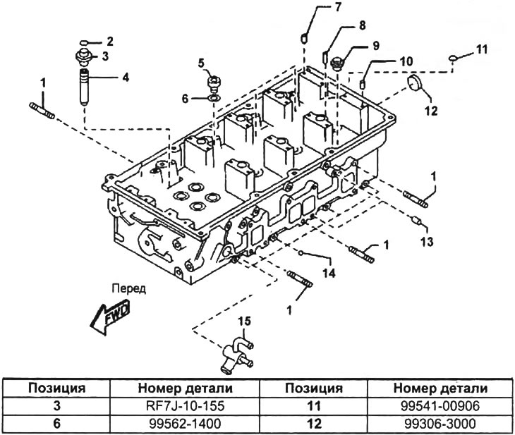
Cylinder head.
1 - hairpin,
2 - retaining ring,
3 - oil scraper cap,
4 - valve guide sleeve,
5 - valve,
6 - gasket,
7, 8, 10 - pin,
9 - threaded plug,
11 - sealing ring,
12 - sealing plug,
13 - plug,
14 - steel ball,
15 - branch pipe of the cooling system.
If the amount of flatness exceeds the maximum allowable value, replace the cylinder head or grind it.
- Grinding amount - 0.15 mm
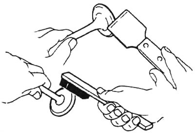
6. Clean the valves.
A) Use a scraper to remove carbon deposits from the valve disc.
b) Completely clean the valve with a brush.
7. Check and lap the valves.
A) Check the thickness of the cylindrical part of the valve disc.
Valve plate thickness:
- inlet - 1.55 - 1.85 mm
- release - 1.80 - 2.10 mm
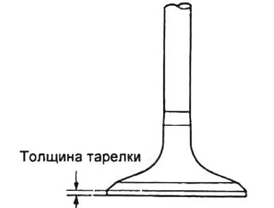
If the thickness of the cylindrical part of the valve disc is less than the specified value, then replace the valve.
b) Check overall valve length.
Nominal length:
- intake - 111.65 -112.25 mm
- release - 111.6 - 112.2 mm
Minimum length:
- intake - 111.50 mm
- release - 111.44 mm
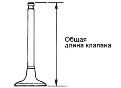
If the overall length is less than the minimum, replace the valve.
V) Check the condition of the valve faces for wear.
If the valve face is worn, regrind the valve face or replace the valve.
G) Using a bore gauge, measure the inside diameter of the valve guides in three levels and two planes.
- Nominal diameter - 6.025 - 6.045 mm
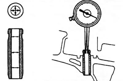
If necessary, replace the valve guide,
d) Using a micrometer, measure the diameter of the valve stem in three levels and two planes.
Nominal diameter:
- inlet 5.970 - 5.985 mm
- release - 5,965 - 5, 980 mm
Minimum Diameter:
- intake - 5.920 mm
- release - 5.915 mm
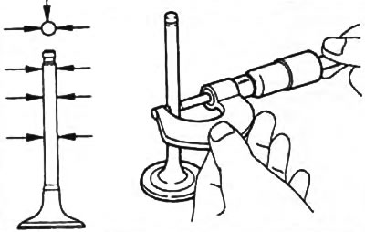
Replace valve if necessary.
8. Check the valve face for damage. If necessary, use a valve seat burr or valve lapping tool to obtain the desired profile.
- Apply a thin coat of white to the valve seat. Press the valve face against the seat, but do not rotate the valve. Then remove the valve and inspect the valve seat and bevel.
- If the paint remains around the entire circumference (360°) chamfers of the valve, the valve is concentric. Otherwise, replace the valve.
- If the paint appears around the entire circumference (360°) valve seats, valve guide and valve seat are concentric. Otherwise, regrind the bevel.
- Make sure that the contact patch is in the middle of the valve face and has a normal width.
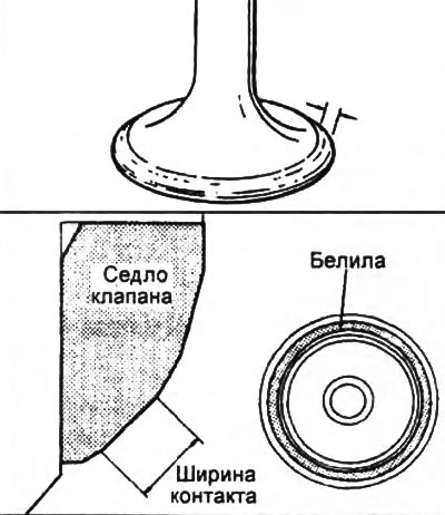
- Normal contact patch width - 13 - 1.9 mm
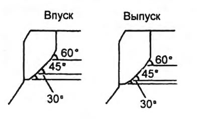
Otherwise, adjust the chamfer as follows:
- If the contact patch is too high on the valve face, use 60°and 45°cutters to regrind the seat.
- If the contact patch is too low on the valve face, use 30°and 45°cutters to regrind the seat.
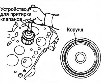
9. Lap the valve. To lap the valve, apply a thin layer of engine oil mixed with a small amount of corundum to the seat surface, and then, tapping lightly, rotate the valve. After lapping, clean the valve and valve seat.
Attention:
- When lapping the valve, be careful and careful that the corundum does not stick to the valve stem.
- The position of the valve contact relative to the valve seat must be at the center of the circle, and the contact width must be standardized.
10. Check up position of a plate of the valve concerning the plane of a head of the block of cylinders.
Rated Clearance:
- inlet - 0.79 - 1.27 mm
- release - 0.84 - 1.32 mm
Max Clearance:
- intake - 1.68 mm
- release - 1.73 mm
If the clearance is greater than the maximum, replace the cylinder head.
11. Check the valve springs.
A) Using a metal square (90°), check for non-perpendicularity of the spring.
- The maximum allowable non-perpendicularity is 1.60 mm (2°)
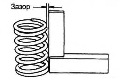
If the deviation from perpendicularity is out of tolerance, replace the spring,
b) Using a spring tester, measure the force required to compress the spring to a setting length of 39.0 mm.
- Force - 172.9 - 195.6 N
If the force is out of range, replace the valve spring.
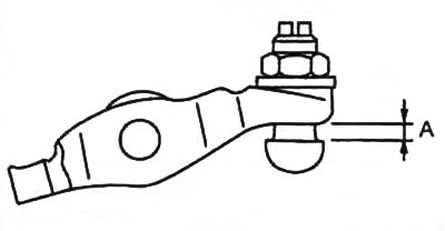
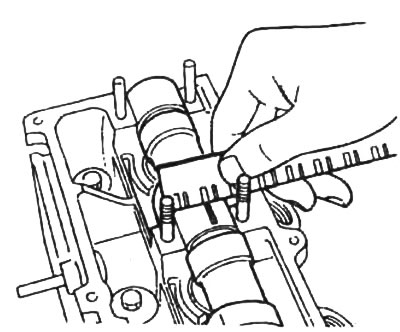
12. Check clearance between adjusting screw and rocker as shown. If the gap is not within specification, adjust it.
- Rated clearance "A" — 0 - 4 mm
13. Check up a camshaft and bearings.
A. Check the camshaft for bending,
A) Lay the camshaft on the prisms.
b) Use a dial gauge to check the camshaft runout relative to the middle journal.
- Maximum runout - 0.03 mm
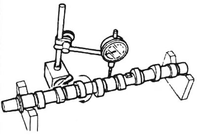
If the runout exceeds the allowable value, replace the camshaft.
B. Measure the camshaft lobe height.
Rated Height:
- intake - 42.067 - 42.167 mm
- release - 41.949 - 42.049 mm
Minimum Height:
- intake - 41.717 mm
- release - 41,599 mm
If the cam height is less than the minimum, replace the camshaft.
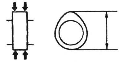
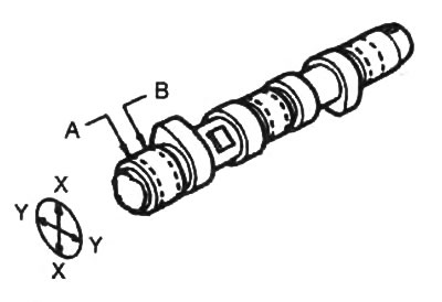
B. Measure the diameter of the camshaft bearing journals at the locations shown in the figure. If the diameter is less than the minimum, replace the camshaft.
Nominal diameter:
- neck #1 - 31.940 - 31.965 mm
- necks N92 - №4 - 25.910 - 25.935 mm
- neck #5 - 25.940 - 25.965 mm
Minimum Diameter:
- Neck No. 1 - 31.890 mm
- necks No. 2 - No. 4 - 25.860 mm
- Neck No. 5 - 25.890 mm
D. Check the radial oil clearance in the camshaft bearings.
A) Clean the camshaft and cylinder head beds.
b) Place a plastic gauge on each camshaft bearing journal.
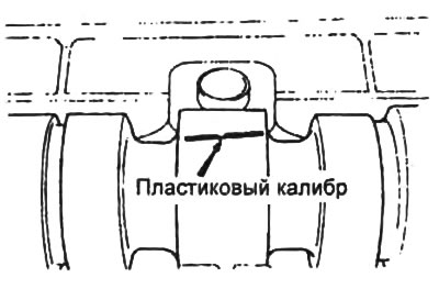
V) Install the camshaft bearing caps (see chapter "Engine. Mechanical").
- Tightening torque - 8-10 Nm
G) Remove the camshaft bearing caps (see chapter "Engine. Mechanical").
d) By measuring the width of the caliber, determine the gap
Rated Clearance:
- neck No. 1 - 0.035 - 0.081 mm
- necks No. 2 - No. 4 - 0.065 - 0.111 mm
- neck No. 5 - 0.056 - 0.081 mm
Max Clearance:
- neck N91 - 0.12 mm
- necks No. 2 - No. 4 - 0.15 mm
- neck No. 5 - 0.16 mm
If the clearance exceeds the specified limit, replace the cylinder head and camshaft.
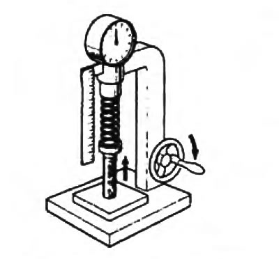
D. Check the camshaft end play. To do this, install the camshaft. Use an indicator to measure the axial clearance while moving the camshaft back and forth.
Axial clearance:
- nominal - 0.03 - 0.16mm
- maximum - 0.20 mm
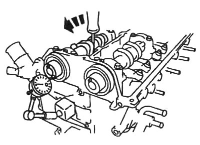
If the axial clearance is greater than the maximum, replace the camshaft or cylinder head.