A) Check each cylinder for damage or cracks. Replace the cylinder block if necessary.
b) Remove the remnants of gaskets from the working surfaces of the cylinder block.
V) Clean the cylinder block with solvent and a soft brush.
2. Check the gas joint surface of the cylinder block for flatness using a precision ruler and a flat feeler gauge as shown in the figure.
Attention: regrinding of the surface of the cylinder block is not allowed.
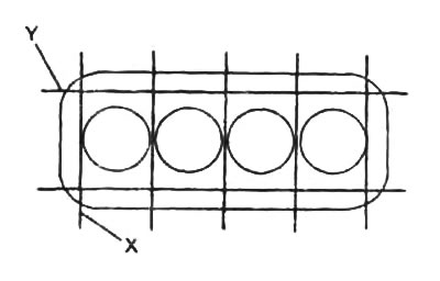
Maximum non-flatness:
- towards "X" - 0.02 mm
- towards "Y" - 0.05 mm
If the flatness exceeds the specified value, replace the cylinder block.
3. Check up a mirror of cylinders on presence of vertical scratches. If possible, bore the cylinder block to the next oversize. If there are deep scratches, replace the cylinder block.
4. If necessary, remove the wear step into the upper compression ring stop umbrella at TDC.
5. Using an inside gauge, measure the cylinder diameter as shown in the figure.
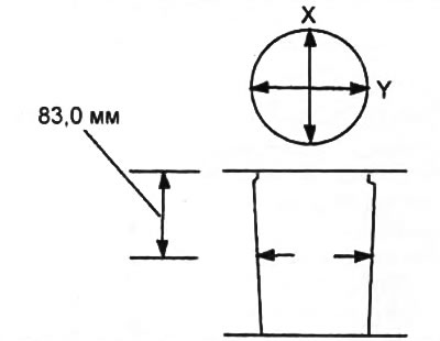
Cylinder diameter:
nominal - 93,000 - 93,022 mm
repair size:
- (0,25) - 23.250-93.272 mm
- (0,50) - 93.500-93.522 mm
Maximum wear value - 0.15 mm
If the diameter is greater than the maximum, bore all cylinders to the oversize or replace the cylinder block.
6. Check oil nozzle bypass bolt.
A) Apply pressure to the oil injector bypass bolt from the side "A".
- Pressure - 138-196 kPa
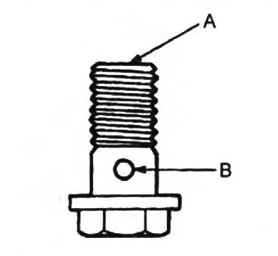
b) Check that air is escaping from the side Replace "IN". Otherwise, the bypass bolt.
7. Check up size of an axial backlash of a rod bearing.
Attention: before measuring the clearance, install the connecting rod cap.
Axial clearance:
- nominal - 0.110-0.260 mm
- maximum - 0.35 mm

If the end play is greater than the maximum, replace the connecting rod assembly.
Replace crankshaft if necessary.
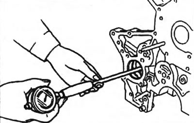
8. Remove the cover of the lower head of the connecting rod and check the radial clearance of the connecting rod bearing.
A) Remove the two connecting rod cap bolts.

b) Using a plastic-faced hammer, lightly tap the connecting rod bolts and remove the lower connecting rod cap by rocking it from side to side.
Note: The lower bearing must remain in the connecting rod cap!
V) Clean the crankpin and bearings.
G) Check the surfaces of the crankpin and bearing for pitting and scratches.
If there are scratches or scratches, replace the bearings. Regrind journals or replace crankshaft if necessary.
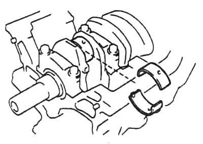
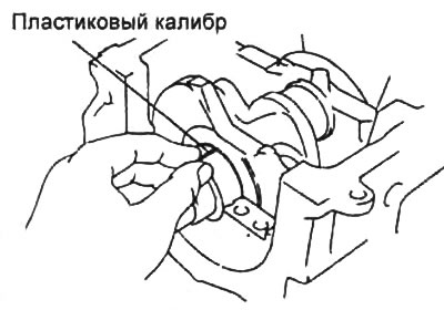
d) Install a plastic bearing clearance gauge as shown.
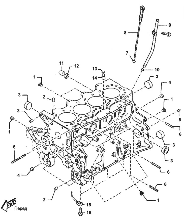
Cylinder block.
1 - threaded plug for hexagon,
2 - hollow pin,
3 - sealing plug,
4 - plug,
5 - locating pin,
6 - hairpin,
7, 10, 13 - sealing ring,
8 - oil dipstick,
9 - oil dipstick guide tube,
11 - cover,
12 - collar,
14 - valve,
15 - oil nozzle,
16 - bypass bolt.
e) Establish a cover of the lower head of a rod and tighten bolts of fastening.
and) Remove the connecting rod cap.
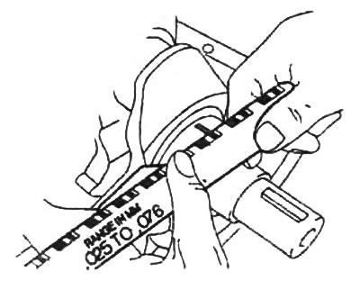
h) Measure the width of the flattened plastic gauge at its widest point and determine the connecting rod bearing clearance.
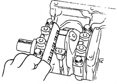
- Nominal clearance - 0.025 - 0.052 mm
- Maximum clearance - 0.08 mm
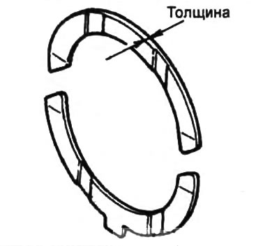
Insert thickness
connecting rod bearings:
- nominal size - 1.507 - 1.516 mm
repair size:
- (0,25) - 1.624-1.634 mm
- (0,50) - 1.749-1.759 mm
- (0,75) - 1.874-1.884 mm
If the end play is greater than maximum, replace the connecting rod bearings or grind the crankshaft journal and install oversize connecting rod bearings.
And) Remove any remaining plastic gauge from the working surfaces of the neck and insert.
9. Check the balance shafts.
A) Install the balancer shafts and tighten the thrust plate mounting bolts.
- Tightening torque - 8-11 Nm
b) Measure the axial clearance of the balance shafts.
- Nominal clearance - 0.04-0.16 mm
If necessary, replace the thrust washer or thrust plate. If the gap is still not within the specified limits, replace the balance shaft or cylinder block,
V) Measure the journals of the balancer shafts in two mutually perpendicular planes in the directions "X" And "Y", as it shown on the picture.
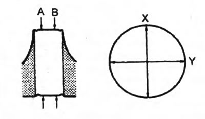
Nominal diameter:
- Neck No. 1 41.945 - 41960 mm
- neck N92 - 30.450 - 39.960 mm
- Neck No. 3 - 37.975 - 37.990 mm
If necessary, replace the balance shaft.
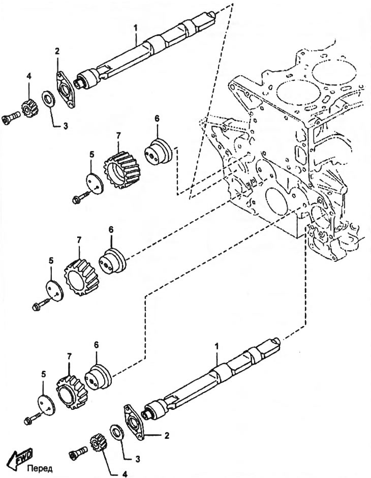
balance shafts.
1 - balance shaft,
2 - thrust plate (P/N - WL84-22-704),
3 - thrust washer (P/N - WL84-11-797),
4 - balance shaft gear,
5 - thrust plate,
6 - intermediate gear hub,
7 - intermediate gear.
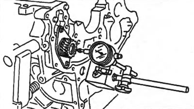
G) Measure the inside diameter of the hole for the balancer shaft in the cylinder block with a bore gauge.
d) Calculate Clearance "balance shaft - hole for balance shaft". If the clearance is greater than acceptable, replace the balancer shaft or cylinder block.
Rated Clearance:
- 1 and 3 necks - 0.050 - 0.115 mm
- 2 neck - 0.080 - 0.145 mm
10. Remove the piston and connecting rod assembly.
A) Remove carbon deposits from the top of the cylinder.
b) Remove the piston assembly with connecting rod and upper bearing shell.
Note: Store pistons with connecting rods, liners, and caps in sets to avoid confusion during installation.
11. Using an indicator, measure the axial clearance of the crankshaft by moving the last "back forward" with a screwdriver.
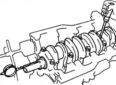
Axial clearance:
- nominal - 0.040 - 0.282 mm
- maximum - 0.30 mm
If the axial clearance is greater than the maximum, replace the thrust washers and/or the crankshaft.
Thickness of thrust half rings:
- nominal size - 0.450 - 2.550 mm
- repair size (0,35) - 2.530 - 2.680 mm
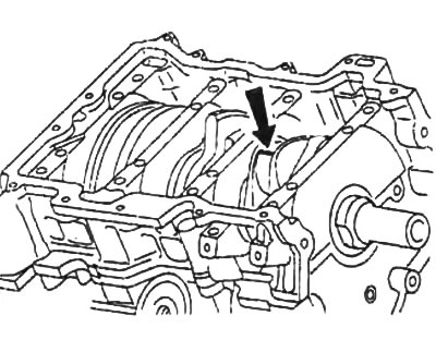
12. Remove the main bearing caps and check the radial oil clearances.
A) Remove main bearing caps (see subsection "Disassembly").
Note:
- Remove the main bearing cap by rocking it slowly from side to side to avoid damaging the mating surfaces of the bearing cap and cylinder block.
- Keep the main bearing caps together with the lower bearings so that they are not mixed up during installation.
b) Raise the crankshaft.
V) Clean each main journal and bearings.
G) Check the surface of each main journal and bearings for pitting and scratches. If the neck or insert is damaged, replace the inserts. Regrind or replace crankshaft if necessary.
d) Install the upper crankshaft main bearing shells and lay the crankshaft in the cylinder block.
e) Place a plastic bearing clearance gauge on each journal.
and) Install the main bearing caps.
h) Apply a coat of engine oil to the threads and under the heads of the main bearing cap bolts and tighten the bolts (see subsection "Assembly").
And) Remove main bearing caps (see subsection "Disassembly").
To) Measure the maximum width of the flattened plastic gauge to determine the radial oil clearance.
Rated Clearance:
- necks No. 1, 2, 4, 1 - 0.021 - 0.041 mm
- neck No. 3 - 0.044 - 0.062 mm
Maximum clearance - 0.08 mm
Thickness of main bearing shells:
- Nominal size - 2.006-2.021 mm
Repair size:
- (0,25) - 2.124 - 2.134 mm
- (0,50) - 2.249 - 2.259 mm
- (0,75) - 2.314 - 2.364 mm
If the oil clearance is greater than the maximum, replace the bearings. Regrind or replace crankshaft if necessary.
l) In the event that the clearance exceeds the limit even if the main bearing is replaced, repair the crankshaft by grinding and use oversize bearings.
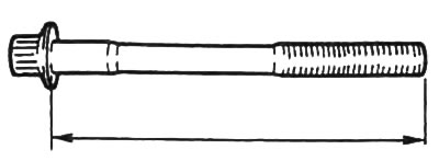
13. Check up length of each bolt of fastening of covers of radical and rod bearings. If the maximum value is exceeded, replace the bolt.
Main bearing cap bolts:
- normal length - 84.1 - 81.3 mm
- maximum length - 86.0 mm
Connecting rod bearing cap bolts:
- normal length - 55.45 - 56.05 mm
- maximum length - 16.11 mm