
Cleaning
2. Clean all traces of old gasket material and sealant from the cylinder head gasket, intake manifold and exhaust manifold sealing surface (photo). Be careful with the soft aluminum cylinder head. Use a special solvent to remove the gasket.
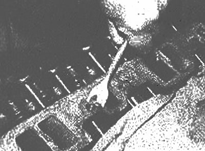
Use a scraper to remove all of the old gasket material
3. Remove all deposits around the cooling channels. liquids.
4. Run a stiff wire brush through the oil holes to clean them.
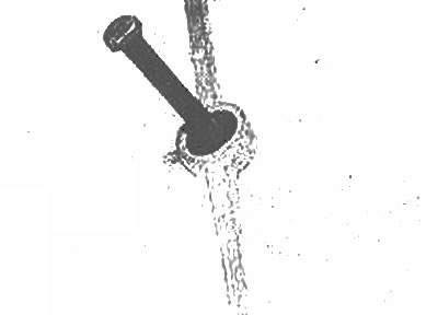
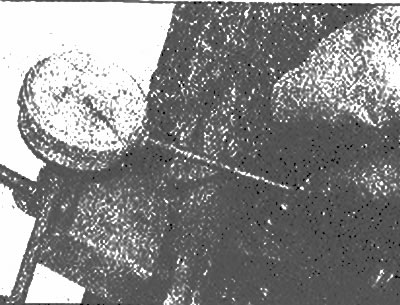
5. Screw an appropriately sized plug into each of the screw holes to remove all corrosion from the threads (photo). If you have compressed air, use it to clear the holes of dirt (photo).
Use a cork to remove old sealant and rust along the entire length of the bolt and hole | 
After draining the liquid from the bolt hole and the rack, use compressed air to remove the dirt formed during cleaning |
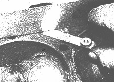
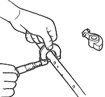
6. Clean the threads of the exhaust and intake manifolds with an appropriate size die (photo).
To clean the thread of the bolt from the seal, you can use a die
7. Clean the cylinder head with solvent and dry thoroughly. Compressed air will speed up the drying process, also check that all holes and grooves are clean.
Note: Carbon deposits are also recommended to be removed with chemical solvents. They are very active and must be used with care. Read the instructions for use on the container.
8. Clean the rocker arms and shafts thoroughly. Compressed air can be used to blow out all lubrication channels.
9. Clean the valve springs, retainers and valve cotters with solvent and dry them thoroughly. Only work with one valve set at a time to avoid overgrading.
10. Clean the components of any heavy particles that have formed on the valves, then use a wire brush to remove the formations from the valve heads and stems.
Inspection
Cylinder head
11. Inspect the head for cracks, signs of coolant leakage. liquid or other damage. If cracks are found, the cylinder head must be replaced.
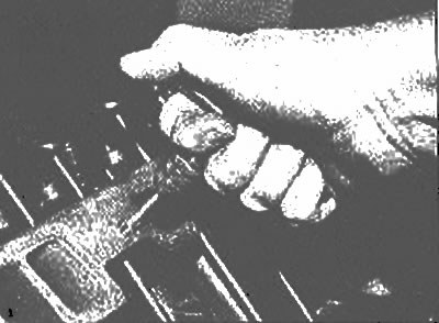
12. Using a ruler and feeler gauge, check the contact surface of the cylinder head gasket for distortion. If the distortion is more than 0.15mm, it can be finished in a mechanical workshop (photo).
Place a standard ruler along the head, and using a feeler gauge, check for distortion | 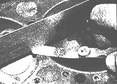
Re-check the linearity of the head of the block, laying the reference ruler from one corner to another |
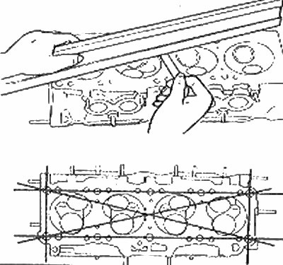
Check the cylinder head for distortion with a standard ruler and feeler gauge at the indicated locations (Chapter 8) | 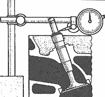
With a micrometer, you can determine the gap between the stem and the valve guide |
Measure the rocker shaft and rocker bore to determine clearance
13. Inspect the valve seats in each of the combustion chambers. If they are distorted, split, then the head requires repair, which can only be done in a specialized workshop.
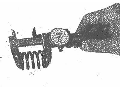
14. Check valve guide and valve stem clearance. Using a micrometer, measure the lateral movement of each valve stem with the valve in the guide and approximately 0.5 cm from the seat (photo). If, after this check, there is still some doubt about the condition of the valve guides, clearance accuracy and the condition of the guides, they can be checked in a car workshop.
Place a stem micrometer on the head against the valve just above the valve guide, lift the valve slightly off the seat, then shake it back and forth to check the valve stem clearance | 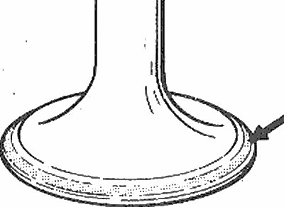
Edge Width (arrow) on each valve must correspond Specifications. Otherwise, the valve must be replaced |
Rocker components
15. Check the rocker surfaces where they come into contact with the camshaft and valve stems for signs of pitting, wear. Also check the contact surfaces of the shaft.
16 Inspect the shaft, mating surfaces for signs of seizing and excessive wear. Measure the clearance between the shaft and rocker arm contact surfaces to ensure clearance is within Specifications.
17. Any damaged or excessively worn parts must be replaced with new ones.
Valves
18. Carefully inspect each facet of the valve for signs of cracks, depressions. Check valve stem. Rotate the valve and check it for distortion. Check the end of the rod for signs of gouges and excessive wear. The presence of any of these conditions indicates the need for valve replacement.
19. Measure the width of the flap edge on each flap, and compare it with specifications. Any valve with an edge that exceeds the value specified in Specifications must be replaced with a new one.
Valve components
20. Check each valve spring for wear (at the ends) and recesses. Measure the free length and compare it with the specifications (photo). Springs shorter than those specified in the Specifications, sagging and distorted, must not be reused. To check the evenness of the spring, use a flat surface of the bed (photo).
Measure the free length of each valve spring. Broken springs need to be replaced | 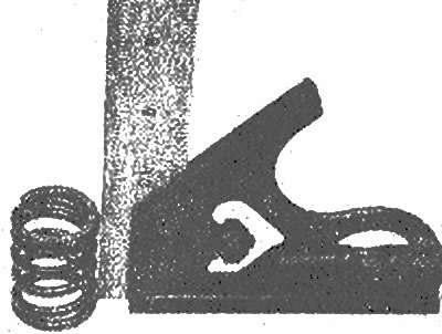
Check each valve spring for squareness, and replace distorted |
21. Check the spring retainers for evidence of wear and cracks. Any questionable components should be replaced with new ones as they can cause severe engine damage.
22. If the check revealed serious wear or damage to the components of the gas distribution mechanism, then before replacing the component, first eliminate the causes that caused these damages.
23. If the wear is insignificant, and all elements are in good condition, then they can be reinstalled. Refer to the relevant chapter for the cylinder head installation procedure