MazBook.ru
English Русский
Български
Беларускі
Український
Српски
Hrvatski
Română
Polski
Slovenský
Magyar
• Bookmark • Sitemap • Contacts •   
Cars Opel Cars Ford Cars Volkswagen Cars Audi Cars Kia Cars Renault Cars Peugeot


Familia Capella Mazda3 Mazda6 CX-? Others Articles
Capella 3 (1982-1992, petrol) Capella 3 and 4 (1982-1992) Capella 4 (1987-1992) Capella 5 (1991-1997) Capella 6 (1997-2005, petrol)

Piston/connecting rod assembly — inspection (Mazda Capella GC)

  • Home
  • Mazda Capella
  • Capella GC (1982-1992)
  • Power unit
  • Engine overhaul
  • Piston/connecting rod assembly — inspection
0
1. Before inspection, the piston/connecting rod assembly must be cleaned and the piston rings removed from the pistons.

Note: Always use new piston rings when reassembling the engine.


2. Using a piston ring installation tool, carefully remove the rings from the pistons. Do not make any nicks or gouges in the piston during the process. If you do not have such a tool, install the piston rings using three old feeler gauges or similar thin metal strips. Carefully spread the ends of the top ring and insert the blades between the ring and the piston, then release the ring along the blades and remove it. Repeat with the other two rings, using the paddles to prevent the lower rings from falling into the upper grooves. Since the rings are meant to be replaced, it doesn't matter if they are accidentally broken, but the experience gained from successful removal will be invaluable when it comes time to install new rings.

3. Clean all traces of carbon from the top of the piston. A wire brush or fine sandpaper can be used for this purpose. Do not, under any circumstances, use a wire brush attached to a power drill to remove deposits from pistons. The piston material is soft and can be easily destroyed with a wire brush.

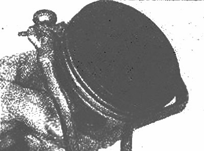
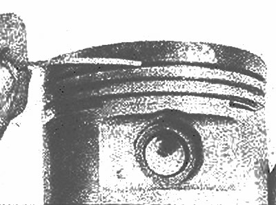
4. Using a special tool for cleaning the grooves under the piston rings, remove all carbon deposits from the grooves. If the tool is not available, a piece cut from the old ring will serve as a substitute. Work very carefully, do not remove metal or nick or scratch the walls of the ring grooves (photo). Wear protective gloves—the old ring fragment has sharp edges.


Use a piece of an old ring to carefully remove carbon deposits from the ring grooves

Use a piece of an old ring to carefully remove carbon deposits from the ring grooves
If possible, clean the ring groove with a special tool

If possible, clean the ring groove with a special tool

5. After removing the carbon deposits, clean the piston/connecting rod assembly with solvent and dry it thoroughly. Make sure that the return lubrication holes in the walls of the annular grooves are not clogged (photo).
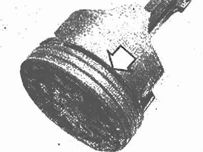
Make sure that the oil return holes in the oil scraper ring groove are not clogged

Make sure that the oil return holes in the oil scraper ring groove are not clogged


6. If the pistons are not damaged or excessively worn, and if the cylinder block does not require regrinding, there is no need to replace the pistons. Typically the side bearing surface of the piston wears out and a small amount of play appears in the upper ring in the groove. It is recommended to install new piston rings.

7. Carefully inspect the skirt, as well as the piston pin mounting areas and the ring grooves of each piston for cracks.

8. Inspect the thrust surface of the skirts for scratches and abrasions, and the piston heads for burnt areas. If the skirt is scuffed or scratched, the engine may have been overheating, which could be caused by a problem with the cooling or lubrication system, or improper ignition timing. Check the cooling and lubrication systems thoroughly. The presence of burnt indentations in the piston head indicates incorrect ignition timing adjustment. Burnt edges of the piston crown usually indicate detonation. If such damage is detected, it is necessary to identify and eliminate its causes, otherwise the damage will occur again.

9. Piston corrosion (usually pointwise) indicates that coolant is entering the combustion chamber and/or crankcase. The cause must also be identified and corrected.

10. Measure the piston ring side clearance by placing a new piston ring in each groove and inserting a feeler gauge between the ring and the wall of the ring groove (photo). Measure the clearance in three or four places in each groove. Make sure you install the corresponding ring in each groove - they are different. If the side clearance is greater than specified in Specifications, replace the pistons.
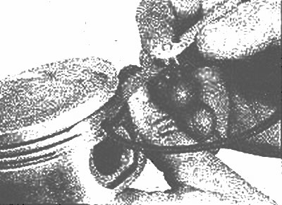


Insert the ring into the groove, then measure the ring gap with a feeler gauge

Insert the ring into the groove, then measure the ring gap with a feeler gauge


11. Check the clearance between the piston and the cylinder wall by measuring the cylinder bore diameter and the piston diameter (see Chapter 14). Do not confuse pistons and cylinders, they form a matched pair. Measure the piston across the skirt (photo). Subtract the piston diameter from the cylinder bore diameter to calculate the clearance. If it is more than specified in Specifications, the cylinder block must be bored and new pistons and rings must be installed. (The clearance between the piston and the cylinder wall can be measured (less accurately) using a feeler gauge, installing the piston without rings into the cylinder bore.)
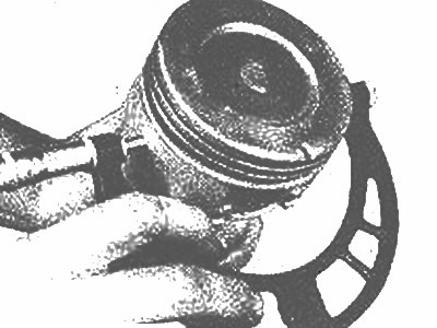
Measure the piston diameter at 90° from the piston pin hole

Measure the piston diameter at 90° from the piston pin hole


12. Check the lateral play of the pivot pin axis by turning the piston and connecting rod in opposite directions. Any noticeable play indicates excessive wear. In this case, the connecting rod/piston bores will need to be re-ground and new piston pins installed - please consult a specialist.

13. If it is necessary to remove the pistons from the connecting rods, for example to replace the pistons or piston pins, contact a service station. At the same time, it is recommended to check the connecting rods for deformation (the station has the appropriate equipment).

14. Inspect the connecting rods for cracks and other damage. Temporarily remove the connecting rod caps, remove the bearing shells, wipe the working surfaces of the connecting rods and caps and inspect them for nicks and scratches. Replace the old bearings, install the caps and tighten the nuts by hand.
This article is available at: russian, bulgarian, belarusian, ukrainian, serbian, croatian, romanian, polish, slovak, hungarian
This text was checked by: Evdokia Filimonova
Share with friends on social networks:

Previous
Capella 3 » Engine overhaul
Next

Camshaft — inspection
Engine block — inspection
Engine block — cleaning
Crankshaft — removal
Cylinder block, crankshaft, bearings and connecting rod parts
Crankshaft — inspection
Main and connecting rod bearings — inspection
Piston rings — installation
Crankshaft — installation and control of main bearing clearance
Piston/connecting rod assembly — installation and checking of bearing…
More articles on repairing other Mazda models
Disconnecting and connecting cable plugs Mazda Familia 6 (1989-1994)
Table 1.5. Piston characteristics Mazda3 BK (2003-2009)
Piston — design description Mazda6 GG (2002-2008)
Disassembling the cylinder block and connecting rod and piston group Mazda CX-5KE (2012-2017)
Disassembling the piston-connecting rod unit of the cylinder block Mazda BT-50 (1) (2006-2011)
Link in different formats to this article
Comments and feedback from visitors
No comments yet


How much will 16 + 44 ?


Capella 6 (1997-2005, petrol) 
  • General information
  • Introduction to guide
  • User manual
  • Troubleshooting
  • Maintenance
  • Power unit
  • 4-cylinder engines
  • 6-cylinder engines
  • Engine overhaul
  • Cooling and ventilation
  • Power and exhaust systems
  • Engine electrics
  • Control system
  • Transmission
  • Mechanical gearbox
  • Automatic gearbox
  • Clutch and drive shafts
  • Chassis
  • Brake system
  • Car suspension
  • Steering
  • Body
  • Exterior (external elements)
  • Interior (internal elements)
  • Doors, windows and locks
  • Electrical equipment
  • Equipment and devices
  • Electrical circuits
Capella 5 (1991-1997) 
  • General information
  • User manual
  • Maintenance
  • Helpful hints
  • Power unit
  • Petrol engines 1.6 and 1.8
  • Petrol engines 2.0
  • 2.5 petrol engines
  • Overhaul engines 1.6 and 1.8
  • Overhaul engines 2.0 and 2.5
  • Diesel engine 2.0
  • Engine electrics
  • Cooling system
  • Air conditioner
  • Carburetor Nikki 30/34
  • Power system (1.6 and 1.8)
  • Power system (2.0 and 2.5)
  • Control system
  • Transmission
  • Mechanical gearbox
  • Automatic gearbox
  • Clutch and axles
  • Chassis
  • Brake system
  • Suspension and wheels
  • Steering
  • Body
  • Exterior (external elements)
  • Interior (internal elements)
  • Doors and windows
  • Electrical equipment
  • Equipment and devices
  • Electrical circuits
Capella 4 (1987-1992) 
  • General information
  • Introduction to manual
  • Vehicle specifications
  • Power unit
  • Engine repair
  • Lubrication system
  • Cooling system
  • Fuel system (carburetor)
  • Fuel injection (FE)
  • Fuel injection (DOHC)
  • Fuel system (diesel)
  • Ignition system
  • Transmission
  • Clutch
  • Gearbox
  • Drive shafts
  • Chassis
  • Front suspension
  • Rear suspension
  • Steering system
  • Brake system
  • Electrical equipment
  • Equipment and devices
  • Electrical circuits
Capella 3 and 4 (1982-1992) 
  • General information
  • User manual
  • Maintenance
  • Power unit
  • Gasoline engine
  • Engine overhaul (gasoline)
  • Diesel engine
  • Cooling and heating
  • Supply system
  • Ignition system
  • Emission reduction
  • Transmission
  • Clutch
  • Mechanical gearbox
  • Automatic gearbox
  • Drive shafts
  • Chassis
  • Brake system
  • Suspension and wheels
  • Steering
  • Body
  • Exterior (external elements)
  • Interior (internal elements)
  • Electrical equipment
  • Equipment and devices
  • Power devices
  • Electrical circuits
Capella 3 (1982-1992, petrol) 
  • General information
  • User manual
  • Maintenance
  • Troubleshooting
  • Late models
  • Power unit
  • Engine in car
  • Engine overhaul
  • Cooling and heating system
  • Fuel and exhaust system
  • Engine electrical system
  • Emission control system
  • Transmission
  • Mechanical gearbox
  • Automatic gearbox
  • Clutch and drive shafts
  • Chassis
  • Brake system
  • Suspension and wheels
  • Steering
  • Body
  • Exterior (external elements)
  • Interior (internal elements)
  • Electrical equipment
  • Equipment and devices
  • Lighting and lamps
  • Electrical circuits
MazBook.ru © 2018–2026 · Mobile version · Articles and news · Sitemap: EN BG BY UA RS HR RO PL SK HU · Feedback · Site search · Add to bookmarks Familia 5 (BF) · Familia 6 (BG) · Capella 3 (GC) · Capella 3 and 4 (GC) · Capella 4 (GD) · Capella 5 (GE) · Capella 6 (GF) · Mazda3 BK · Mazda6 GG · CX-5KE · Mazda 121 (3) · Mazda BT-50 (1) ·
By continuing to use the site, you agree to the use of cookies 🔐