


2. Place the piston/connecting rod assemblies and new rings in the same cylinders.
3. Insert the top ring (No. 1) into the first cylinder, pushing it with the top of the piston (photo). The ring should be near the base of the cylinder. Measure the gap. inserting the feeler gauge between the ends of the ring (photo). Compare the measurement with Specifications.
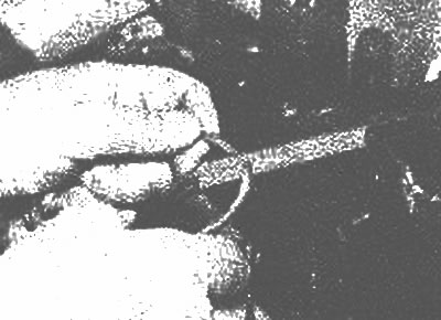
Before checking the piston ring clearance, the ring should be positioned perpendicular to the cylinder liner. This can be achieved by pushing rings into the cylinder with the piston |
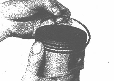
With the ring positioned perpendicularly in the cylinder, measure the gap with a feeler gauge |
4. If the gap is greater or less than that specified in Specifications, then first make sure that you have selected rings of the required repair size.
5. If the gap is too small, it must be increased. The gap is bored out with a fine file clamped in a vice. Place the file in a vice equipped with soft jaws and slowly file down the rings (photo).
To increase the ring clearance, secure a file in a vice and carefully file the ring
6. It is permissible to grind down no more than 1 mm. If you need to grind down more, you are most likely dealing with rings of the wrong repair size.
7. Repeat the procedure for each ring in the first cylinder and for each ring in the remaining cylinders.
8. Once the clearances are set correctly, the rings can be installed on the pistons.
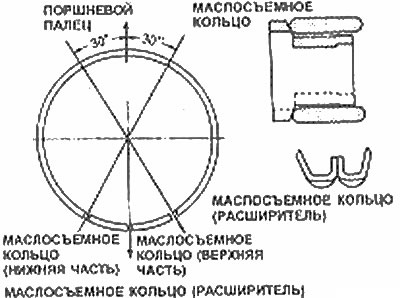
9. Oil scraper ring (the lowest on the piston) is installed first. It is composed of three separate components. Install the spacer/expander into the groove (photo), then install the lower part. Do not use a tool to install the oil scraper ring, as it can be easily damaged. Instead, place one end of the ring into the groove between the spacer/expander and push the other end through (photo). Then, install the top part in the same manner.
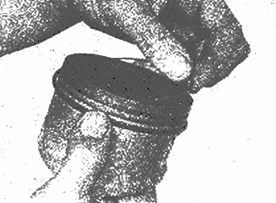
Install the oil scraper ring expander in the lower groove of the piston and check that its ends fit correctly into the lock |
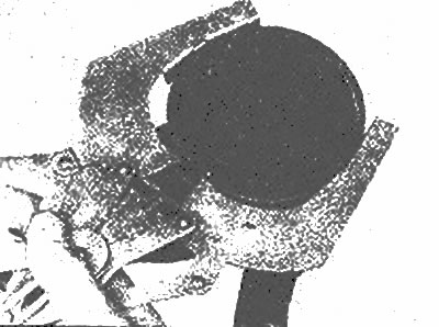
When installing the oil scraper ring, use the ring installation tool |
The article is based on website data [www.MAZbook.ru]
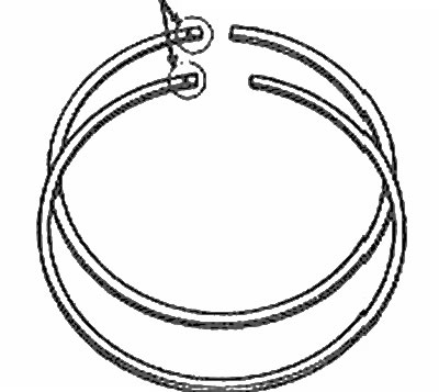
Installation of oil scraper ring and clearance arrangement
10. After the three components of the oil deflector ring are installed, check that both the upper and lower parts rotate freely in the groove. See accompanying illustration for ring installation.
11. Ring No. 2 (middle) is installed next. It is stamped with an R mark, which should face the top of the piston.
Note: Follow the instructions printed on the ring manufacturer's box. Do not swap the top and middle rings as they have different cross sections.
12. Using the piston ring installation tool, ensure that the ring marking faces the top of the piston. install the ring into the middle groove on the piston (photo). Do not expand the ring more than necessary. Instead of a ring installation tool, you can use a feeler gauge - see Chapter 16.
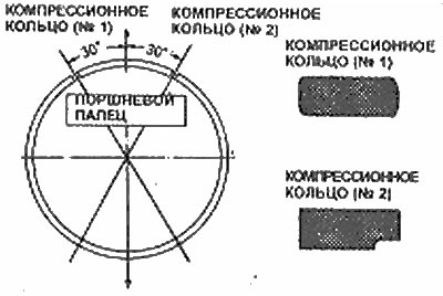
Use a ring expander to install the compression ring
13. Install ring #1 (top) in the same manner. Check that the identification mark is positioned correctly. Be careful not to confuse the ring numbers (#1 and #2). See the corresponding illustration.