
2. Remove the cap from #1 connecting rod. Remove the old bearing shells and wipe the bearing surfaces on the connecting rod and cap with a clean, dense (lint-free) cloth. They must remain spotlessly clean.
3. Clean the back of the new upper bearing shell, then install it in the connecting rod. Make sure the tab on the bushing fits into the notch on the connecting rod. Do not use a hammer when installing the insert. Place the insert carefully into place so as not to damage its surface. Do not lubricate the bearing shell at this stage.
4. Clean the back of the other bearing and install it in the connecting rod cap. Again, make sure that the protrusion of the liner fits into the notch in the cover, and do not lubricate the liner. It is critical that the bearing and connecting rod contact surfaces are perfectly clean and free of grease.
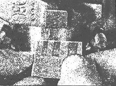
5. Install the piston rings so that their gaps are located as shown in the illustrations, then put a piece of plastic or rubber hose on each connecting rod cap bolt.
6. Lubricate the piston and rings with clean engine oil and install a piston ring extractor on the piston so that the piston skirt protrudes from the extractor by approximately 6 mm to allow the piston to be inserted into the cylinder (photo). Squeeze the rings as far as possible.
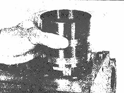
When installing the pistons, make sure that the piston skirt protrudes slightly from the piston ring remover so that the piston can be inserted into the cylinder | 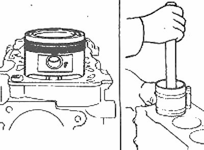
Install the pistons so that the mark «F» was directed towards the front end of the engine |
7. Rotate the crankshaft so that the No. 1 connecting rod journal is as far away from the cylinder as possible (bottom dead center), and lubricate the cylinder walls with engine oil.
8. Gently place the piston/connecting rod assembly into the No. 1 cylinder bore with the notch or arrow on the piston toward the front of the engine. The bottom edge of the piston ring remover must rest against the cylinder block. Tap the top edge of the piston ring remover to make sure it is fully seated on the block. (If there are no notches or arrows on the piston head, make sure the 'F' mark is on before installing the piston ring remover. next to the piston pin locating hole, facing the front of the engine.)
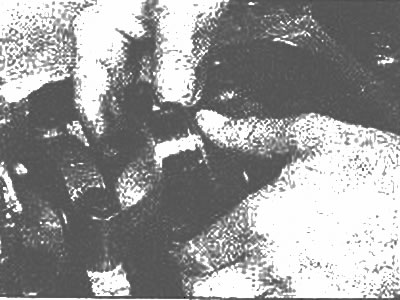
9. Gently tapping the top of the piston with the end of the wooden hammer handle (photo), install the end of the connecting rod on the crankshaft journal. Piston rings may pop out of the piston ring remover before entering the cylinder bore. To avoid this, press the piston ring remover against the cylinder block. Work slowly and if you feel the resistance of the piston, stop immediately. Find out what is preventing the installation and eliminate the cause. Under no circumstances force the piston into the cylinder, otherwise you will break the ring and / or the piston.
Gently insert the piston into the bore of the cylinder by pressing it with the end of the wooden hammer handle
10. Once the piston/rod assembly is in place, check the connecting rod bearing operating clearance before finally installing the connecting rod cap.
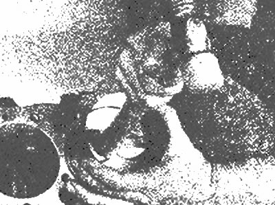
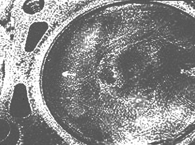
11. Cut off a piece of Plascigage material (tool for measuring clearances in plain bearings) of a suitable size so that it is slightly shorter than the width of the connecting rod bearing, and place it on the journal of the No. 1 connecting rod parallel to the axis of the journal (photo). It must not cross the lubrication hole in the neck.
Place a piece of Plastigago across the crankpin
12. Clear a basic surface of the bearing in a rod cap, remove protective pieces of tubes from rod bolts and establish a cover. Make sure the mark on the cap is on the same side as the mark on the connecting rod. Install the nuts and tighten them in three steps to the specified tightening torque. Do not turn the crankshaft during this operation.
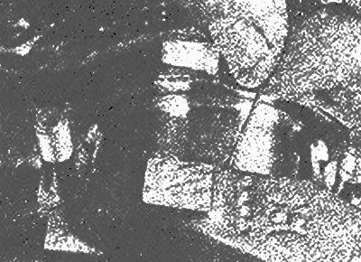
13 Remove the stem cap very carefully so as not to move the Plastigage. Compare the width of the Plastigage with the scale shown on the tool box to calculate the working clearance (photo). Compare the obtained value with the data given in the Specifications. If the gap is not correct, check again that the correct size bearings are installed. Also, re-check the diameter of the crankshaft journal and make sure that no dirt or oil has entered when measuring the clearance between the bearing shells and the connecting rod or cap.
Compare the width of the Plastigago material with the scale to determine the working clearance
14. Carefully clean all traces of Plastigage from the crankpin and/or bearing surface. Be very careful not to scratch the liner, use your fingernail or a piece of wood. Make sure the bearing surfaces are perfectly clean, then apply an even coat of clean, high quality molybdenum grease or special motor assembly machine oil to both surfaces. Push the piston into the cylinder to gain access to the bearing shell surface in the connecting rod. Don't forget to put protective pieces of hose on the rod bolts first (photo).
Use rubber boots to prevent the connecting rod cap bolts from scratching the cylinder walls and crankshaft journal, and install the connecting rod on the journal
15. Reinstall the connecting rod on the neck, remove the protection from the connecting rod cap bolts, install the cover and tighten the nuts in three stages with the tightening torque regulated by the Specifications.
16. Repeat the procedure on the remaining piston/rod assemblies. Maintain cleanliness. Make sure you don't mix up pistons (installed each of them in the corresponding cylinder) and that notch-arrow or mark «F» on the piston is directed towards the front of the engine (photo). Be sure to generously lubricate the piston before installing the piston ring remover on it. Also, when final installation of the connecting rod caps, do not forget to lubricate the bearing surfaces.
The arrow on the piston head must point towards the front of the engine | 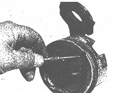
Some pistons have a notch instead of an arrow |
17. After installing all pistons/connecting rods, turn the crankshaft several times by hand to make sure it rotates freely.
18. Finally, check the end play of the connecting rod (see chapter 11). Compare the value obtained with the data given in Specifications.