
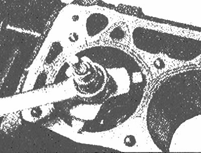
Use the special tool to remove the wear ridge on the top of each cylinder before removing the pistons
2. Before removing the connecting rods, check their play. Install the micrometer so that its shaft is parallel to the crankshaft axis and touches the side of the #1 connecting rod cap.
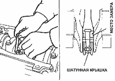
Connecting rod play check
3. Pull the connecting rod back as far as possible and set the micrometer to zero. Then, move the connecting rod all the way forward and record the micrometer reading - this is the amount of play. If the clearance exceeds the wear limit, the connecting rod must be replaced. Repeat the procedure on the remaining connecting rods.
4. Alternate Method: Insert a feeler gauge between the connecting rod and the side of the crankshaft, making sure the feeler gauge is thick enough to eliminate any play in the connecting rod (photo). The backlash is equal to the thickness of the probe.
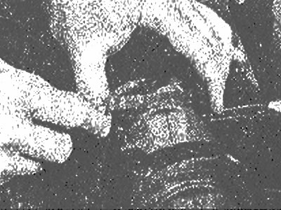
Insert a feeler gauge between the connecting rod and the side of the crankshaft to measure the clearance
5. Check up, whether connecting rods and their covers are numbered. If not, mark each connecting rod and cap with a small punch, making a number of indentations corresponding to the number of the cylinder in which the connecting rod is installed (photo).
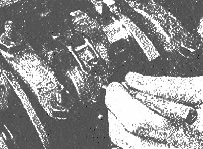
Use a punch to mark the connecting rods before removing them | 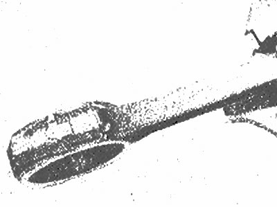
The number of punched recesses must correspond to the number of the cylinder in which the connecting rod is installed, and marks must be made on both the connecting rod itself and on its cover to ensure their correct installation |
6. Loosen each of the connecting rod cap nuts by half a turn. Remove #1 connecting rod cap and bearing shell. Do not let the bearing shell fall out of the cover. Slide a short piece of plastic or rubber tube over each connecting rod cap bolt to protect the crankshaft journal (photo) and push the connecting rod piston assembly through the top of the cylinder. Use a suitable wooden block to rest against the upper bearing shell in the connecting rod. If resistance is felt, re-verify that the entire protrusion formed in the cylinder by wear has been ground off.
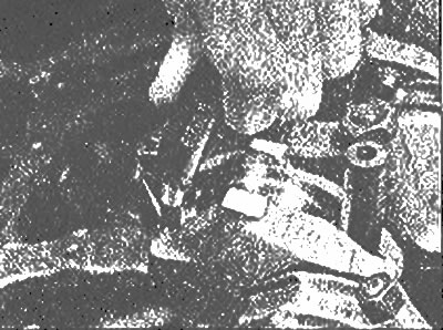
Hold the crankshaft and cylinder walls so as not to scratch the stem bolt threads before removing the rods
7. Repeat the procedure for the remaining cylinders. Once removed, reassemble the connecting rod caps and bearing shells in their respective connecting rods and hand tighten the nuts. Leave the old bearing shells in place until reassembly, which will help keep the connecting rod bearing surfaces free of accidental nicks or gouges.