


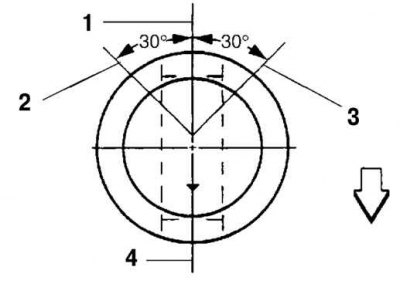
Fig. 2.174. Piston ring lock arrangement diagram: 1 - top ring; 2 – upper oil scraper ring; 3 – lower oil scraper ring; 4 – oil scraper ring expander and second ring
Arrange the ring locks as shown in Figure 2.174.
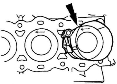
Fig. 2.175. Installing the piston with the connecting rod into the cylinder
Insert the piston with the connecting rod into the cylinder, the arrow mark should be facing the front of the engine (fig. 2.175).