


Install the recirculation tube.
Installing the oil seal
Press the valve stem seal onto the valve guide by hand.
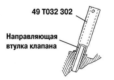
Fig. 2.184. Installing the oil deflector cap
Press lightly with a special device using a nylon hammer (fig. 2.184).
Install the valves, valve springs and upper valve spring retainers.
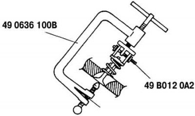
Fig. 2.185. Installing valve crackers
Install the valve crackers using special tools (fig. 2.185).
Install the engine lifting eyes.
Install a new cylinder head gasket.
Installing the cylinder head
Install the cylinder head.
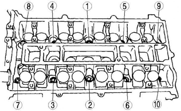
Fig. 2.186. Cylinder head bolt tightening sequence
Tighten the cylinder head bolts in the order shown in Figure 2.186 in six steps.
- Tighten to 5.0 Nm.
- Tighten to 13–17 N·m.
- Tighten to 44–46 N·m.
- Tighten to 88–92°.
- Tighten to 88–92°.
- Tighten completely.
Installing camshafts
Install the camshafts, with the piston of cylinder No.1 set to the TDC position of the compression stroke.
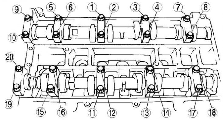
Fig. 2.187. The order of tightening the bolts securing the camshaft bearing caps
Tighten the camshaft bearing cap bolts in two steps (fig. 2.187).
- Tighten to 5.0–9.0 N·m.
- Tighten to 14.0–17.0 N·m.
Assembly instructions for the camshaft sprocket, variable valve timing actuator (L3 with variable valve timing mechanism)
Camshaft Sprocket Bolt or Variable Valve Timing Actuator (L3 with variable valve timing mechanism) temporarily, until the timing chain is installed, it is screwed in manually.
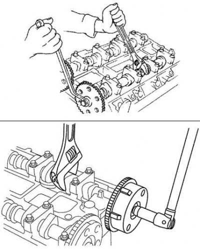
Fig. 2.188. Tightening the camshaft sprocket mounting bolt (conventional engine) and actuator for changing valve timing
Connecting bolt of the camshaft sprocket or variable valve timing actuator (L3 with variable valve timing mechanism) after installation of the timing chain, it is installed with glue (fig. 2.188).
Tightening torque: 69–75 Nm.