
The main functions of the system are the optimal and correct control of the diesel fuel injection process at the right time and in the required quantity, also at the required injection pressure, which is ensured by the use of an electronic control system. Such an organization of the injection process control ensures smooth and economical operation of the diesel engine.
In this common rail fuel system, the fuel pressure can reach 160 MPa.
This system allows to achieve a reduction in the content of particulate soot in exhaust gases and nitrogen oxides NOx.
The common rail common rail fuel system includes: a low pressure stage, a high pressure stage and an electronic engine management system.
The main elements of this system are electro-hydraulic nozzles, injection pumps from Bosch (SRH) (with fuel temperature sensor and fuel pressure control valve), fuel accumulator (with fuel pressure sensor and pressure reducing valve), sensors and valves of the engine management system and an electronic engine control unit.
The low pressure stage consists of the fuel tank, fuel filter and low pressure line piping.
The high pressure stage in a common rail fuel system includes the injection pump, fuel accumulator, injectors, high pressure lines and fuel return lines.
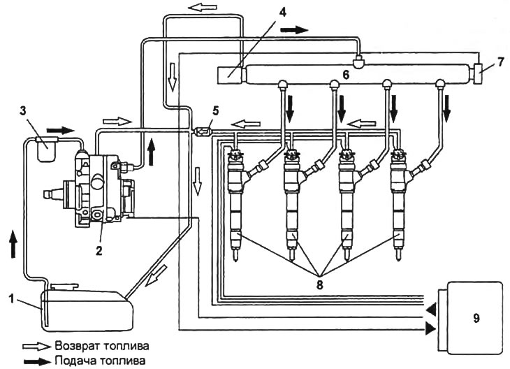
Scheme of common rail fuel system.
1 - fuel tank,
2 - injection pump,
3 - fuel filter,
4 - pressure reducing valve,
5 - control (back) valve,
6 - fuel accumulator,
7 - fuel pressure sensor in the accumulator,
8 - nozzle,
9 - engine control unit.
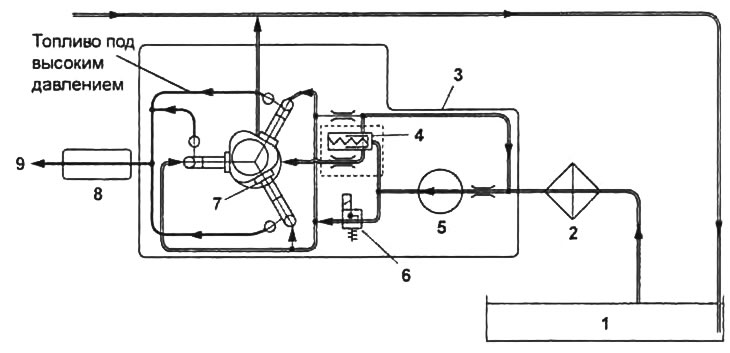
Fuel flow to injection pump.
1 - fuel tank,
2 - fuel filter,
3 - injection pump,
4 - control valve,
5 - fuel priming pump,
6 - fuel pressure control valve,
7 - high pressure chamber,
8 - fuel accumulator,
9 - to the nozzles.
In fitting (2) Injection pump for connecting the fuel supply hose from the fuel tank, an additional fuel filter is installed for better fuel filtration before it is fed into the high-pressure line.
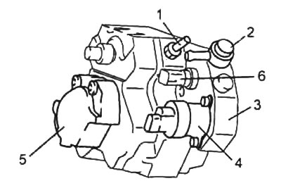
1 - fuel return fitting,
2 - fuel supply fitting from the fuel filter,
3 - injection pump,
4 - fuel pressure control valve,
5 - fuel priming pump,
6 - fuel temperature sensor.
The high pressure fuel pump is driven through a gear system from the crankshaft and delivers fuel at the required pressure to the fuel accumulator. The injection pump includes a fuel priming pump (pumping fuel from the fuel tank into the plunger chamber), fuel temperature sensor, fuel pressure control valve, camshaft and three plungers (located at an angle of 120°relative to each other), pumping fuel at high pressure into the fuel accumulator.
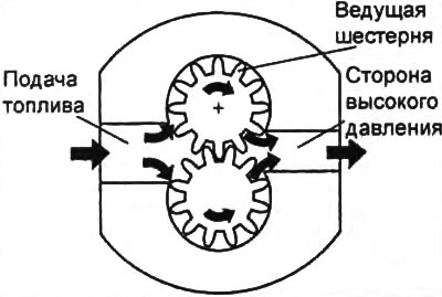
In the high-pressure plunger chambers, the required amount of fuel is pumped from the fuel tank using a gear-type fuel priming pump. The fuel priming pump consists of two gears with external gearing, rotating in different directions. In the pump, fuel from the supply line enters the gap between the gear teeth and the housing and is supplied to the high pressure chamber of the injection pump. The return of fuel to the supply line is excluded due to the tight contact of the gear teeth. Since the speed of rotation of the fuel priming pump depends on the speed of the crankshaft, it becomes necessary to control the amount of fuel pumped into the plunger chambers.
The amount of fuel supplied to the high pressure plunger chamber is controlled by the fuel priming pump control valve. Through this valve, at an increased crankshaft speed, part of the fuel returns to the fuel supply line. The fuel pressure control valve regulates the amount of fuel supplied to the accumulator, thereby maintaining a constant pressure in the fuel accumulator. The valve is controlled by the engine control unit, at the signal of which the valve opens and excess fuel is supplied to the return line.
The fuel supplied from the priming pump passes into the inlet port inside the pump. A safety valve is located behind the inlet. If the pressure created by the fuel priming pump exceeds the opening pressure of the safety valve, then the fuel passes through the valve throttle into the lubrication and cooling circuit of the injection pump. The eccentric drive shaft moves the plunger according to the lift of the eccentric. Fuel flows through the intake valve (1) injection pump in high pressure chamber (5) pump element and, when the plunger moves (8) down implements the intake stroke. Shaft (6) in the injection pump housing is installed in the central bearing. Eccentric (7) on the injection pump shaft provides reciprocating motion of the plungers. After reaching the bottom dead center BDC of the plunger, the inlet valve closes and the fuel can no longer exit the upper chamber of the pump element (plunger). Then, when the plunger moves up, the fuel is compressed, the pressure rises and the exhaust (discharge valve) (2) opens as soon as the pressure exceeds its level in the fuel accumulator. The compressed fuel then enters the high pressure circuit.
The injection pump plunger continues to supply fuel until it reaches the TDC position (injection stroke). After that, the pressure drops, the exhaust valve closes and the plunger moves down. When the pressure in the chamber of the pumping element exceeds the boost pressure, the inlet valve opens again and the process repeats.
The fuel temperature sensor includes a measuring resistor and is powered by 5 V. The resistance of the resistor changes depending on the temperature of the fuel, which in turn affects the output voltage (signal) sent by the sensor to the control unit. The control unit receives a signal from the sensor and determines the temperature of the fuel according to the algorithm stored in its memory. The data received from the fuel temperature sensor is used to calculate the cyclic fuel supply.
High-pressure fuel from the injection pump enters the fuel accumulator, from where it is supplied to the injectors. Optimum pressure is maintained in the fuel accumulator (25 - 160 MPa).
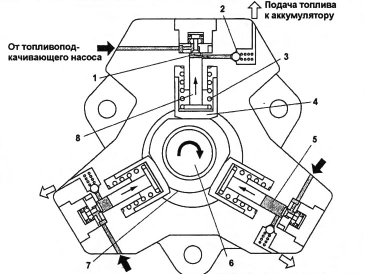
Cross section of the injection pump.
1 - intake valve,
2 - exhaust valve,
3 - spring,
4 - pusher,
5 - high pressure chamber,
6 - drive shaft,
7 - eccentric,
8 - plunger.
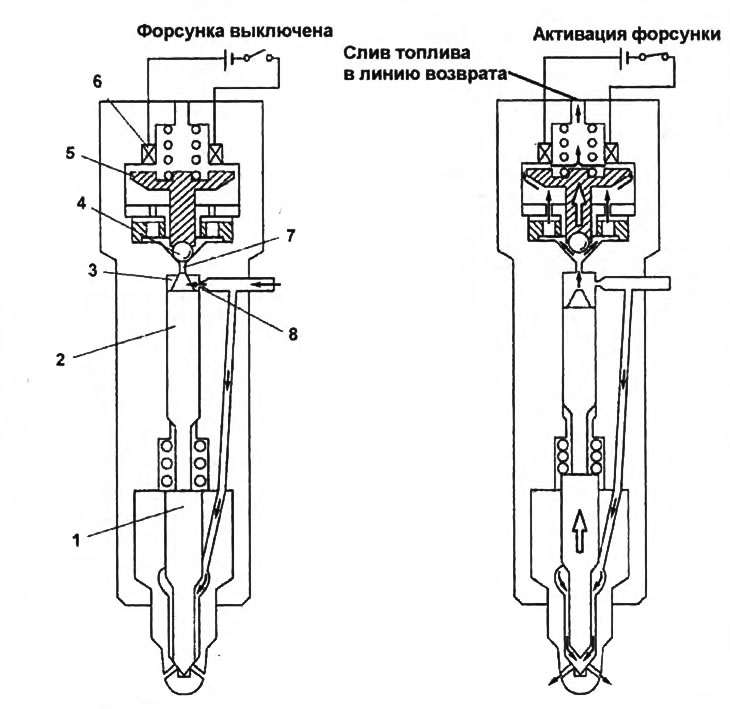
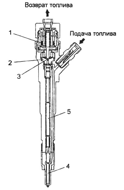
nozzle operation.
1 - needle,
2 - piston,
3 - hydraulic chamber,
4 - ball valve,
5 - solenoid valve anchor,
6 - solenoid valve winding,
7 - return hole,
8 - feed hole.
When the pressure exceeds 195 MPa, part of the fuel is drained through the pressure reducing valve (mounted on a fuel accumulator) to the fuel return line. A pressure sensor is installed on the fuel accumulator.
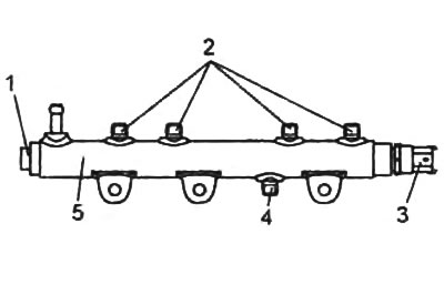
1 - pressure reducing valve,
2 - ports for connecting high-pressure fuel pipes to the injectors,
3 - pressure sensor in the fuel accumulator,
4 - port for connecting a high-pressure fuel pipe for fuel supply from high-pressure fuel pump,
5 - fuel accumulator.
Injectors with an electromagnetic control valve are installed in the system. The injectors are controlled by the engine control unit. Each nozzle consists of a spring-loaded piston (2), needles (1), solenoid valve (6) and hydrochambers (3) (see picture "Nozzle operation"). From the fuel accumulator, fuel is supplied to the nozzle, which enters the hydraulic chamber through the hole (8) and to the nozzle needle. In the hydraulic chamber, the fuel is under pressure equal to the pressure in the fuel accumulator. When the injector is closed, the fuel presses on the spring-loaded piston, which in turn acts on the injector needle, preventing it from opening. When the ECM issues a start control signal to the appropriate injector solenoid valve, the armature is lifted (5) with ball valve (4). Ball valve opens the channel (7), connecting the hydraulic chamber with the fuel return line, as a result of which part of the fuel is drained and the pressure in the nozzle hydraulic chamber is weakened. At the same time, the pressure of the fuel supplied to the nozzle needle overcomes the force of the piston spring and the needle opens, as a result of which the nozzle injects fuel into the cylinder.
A check valve is installed in the fuel return line from the injectors. This valve prevents the return line fuel from the injectors from flowing back to the injectors.
The engine control unit controls the amount of fuel injected and the injection timing. This fuel system can provide up to three consecutive injections (multi-stage injection). Each nozzle is connected to a fuel return line.
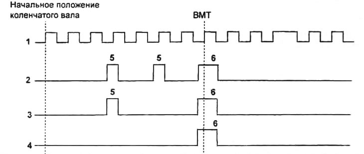
Fuel injection control.
1 - crankshaft position sensor signal,
2 - three injections,
3 - two injections,
4 - one injection,
5 - pilot injection,
6 - main injection.
1 - solenoid valve,
2 - plate with holes,
3 - ball valve,
4 - nozzle needle,
5 - piston.
Fuel injection is controlled by the engine control unit, based on the signals from a number of sensors of the engine management system, as well as depending on the engine operating mode. The control unit controls the amount of injected fuel, injection timing and the number of injections per stroke in each cylinder separately. The amount of fuel injected by the injector is determined by the opening time of the injector needle, which in turn depends on the time during which the engine control unit sends a control signal to the injector solenoid valve. The opening time of the nozzle needle is controlled by the engine control unit depending on the accelerator pedal depression and the crankshaft speed. The calculated amount of injected fuel is corrected based on intake air temperature, air mass flow, coolant temperature and atmospheric pressure. Also, the control unit makes adjustments to the amount of injected fuel for each injector, depending on the injector identification code, which should be programmed into the memory of the engine control unit for each injector separately. This code encodes the mechanical characteristics that are individual for each individual injector.
The engine control unit constantly adjusts the amount of fuel injected into each cylinder depending on changes in the crankshaft speed (especially at idle), to reduce speed fluctuations and reduce vibrations.
The injection timing is calculated by the control unit based on the signals from various sensors, the engine operating mode, the crankshaft speed and the amount of injected fuel according to an algorithm stored in the memory of the control unit. The estimated fuel injection time is corrected based on intake air temperature, coolant temperature and atmospheric pressure.
The injection pressure directly depends on the pressure in the fuel accumulator and is controlled by the engine control unit based on the signal from the pressure sensor in the fuel accumulator.
The fuel pressure is regulated by the control unit depending on the crankshaft speed and cyclic fuel supply using the fuel pressure control valve installed in the injection pump. Creating the optimal fuel injection pressure for each engine operating mode helps to reduce the toxicity of exhaust gases.
The number of injections produced by the injector into the cylinder is controlled by the engine control unit depending on the driving conditions of the vehicle and serves to reduce vibration and exhaust toxicity. This common rail system allows up to three injections per cylinder per cycle.
Several optimal fuel injection algorithms are programmed in the memory of the control unit under various conditions. So, at low crankshaft speed and low load, three injections per cycle are made to reduce the likelihood of detonation. At high engine speed and high load, only one injection per cycle is performed to improve power performance and reduce fuel consumption.
Additional control functions serve to improve the performance in reducing emissions of harmful substances in the exhaust gas and fuel consumption or are used to increase safety, comfort and ease of operation.