


Attention! The actuator of variable valve timing is a precision unit and cannot be disassembled.
Disconnect the negative battery cable.
Remove the plug hole plate.
Remove the high voltage wire.
Remove the oil control valve connector.
Remove the ventilation hose.
Remove the cylinder head cover.
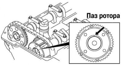
Fig. 2.99. Alignment of the rotor groove with the bulge of the variable valve timing mechanism cover
Make sure that the rotor groove and the bulge of the variable valve timing actuator cover are aligned (Fig. 2.99).
If the groove and the bulge are not aligned, rotate the crankshaft clockwise two revolutions. Check the alignment of the groove and the bulge. If the groove and the bulge are still not aligned, replace the variable valve timing actuator. If the variable valve timing actuator makes a knocking sound when the crankshaft is rotated each time the cam passes the fully open position, the actuator is loose. Replace the actuator.
Install the cylinder head cover.
Install the ventilation hose.
Connect the oil control valve connector.
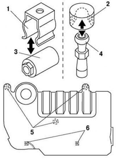
Fig. 2.100. Fastening high-voltage wires: 1 – clamp; 2 – rubber bushing; 3 – wire winding; 4 – nipple tip; 5 – places for installing rubber bushings; 6 – places for installing clamps
Connect the high voltage wire (fig. 2.100).
Install the spark plugs.
Install the plug hole plate.