


Contents: Removal ⇓ Installation ⇓
Attention! The repair operations for the hub and steering knuckle of the left and right front wheels are the same.
Removal
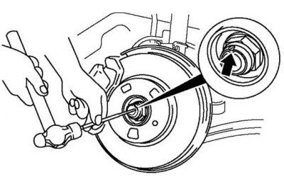
Fig. 3.103. Knocking out the flange of the wheel hub lock nut
Knock out the bent part of the lock nut with a small chisel and hammer (fig. 3.103).
Lock the hub by pressing the brake.
Loosen the lock nut.
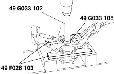
Fig. 3.104. Removing the wheel hub from the drive shaft
Place the hub assembly in a vice. Remove the wheel hub from the drive shaft using special tools (fig. 3.104).
If the inner bearing race remains on the wheel hub axle, cut the inner bearing race to the remaining thickness, (approximately 0.5 mm).
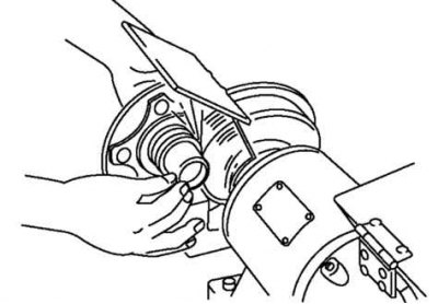
Fig. 3.105. Removing the inner bearing ring
After this, remove the ring with a chisel (fig. 3.105).
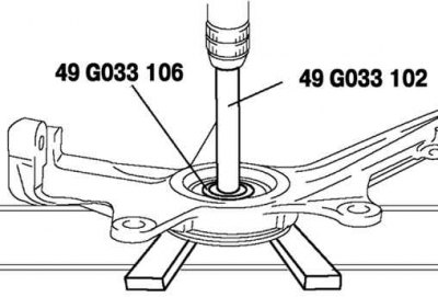
Fig. 3.106. Removing the hub bearing
Remove the wheel hub bearing using special tools (Fig. 3.106).
The article is reprinted from the portal [Mazbook.ru]
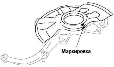
Fig. 3.107. Marking of the hub housing and steering knuckle
Mark the protective cover and steering knuckle for further installation (fig. 3.107).
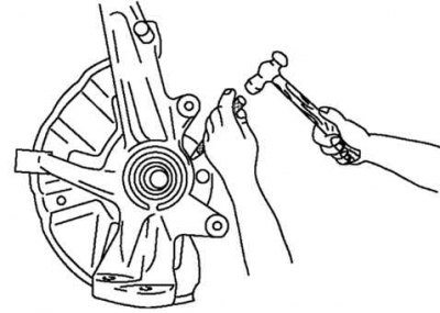
Fig. 3.108. Removing the hub protective cover
Use a chisel to remove the protective cover (fig. 3.108).
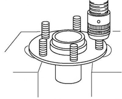
Fig. 3.109. Removing the hub bolts
Place the hub in the press and remove the bolts (fig. 3.109).
Note: The hub bolts should only be removed if they are being replaced.
Installation
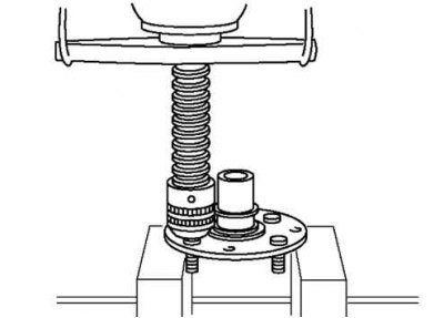
Fig. 3.110. Installing new hub bolts
Use a press to install new hub bolts (fig. 3.110).
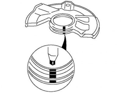
Fig. 3.111. Aligning the marks on the new protective cover and steering knuckle
Install the shroud onto the steering knuckle. Align the marks on the new shroud and steering knuckle (fig. 3.111).
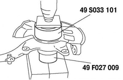
Fig. 3.112. Installing a new protective cover
Using special tools, install a new protective cover (fig. 3.112).
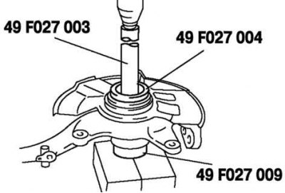
Fig. 3.113. Installing a new wheel hub bearing
Using special tools, install a new wheel hub bearing (fig. 3.113).
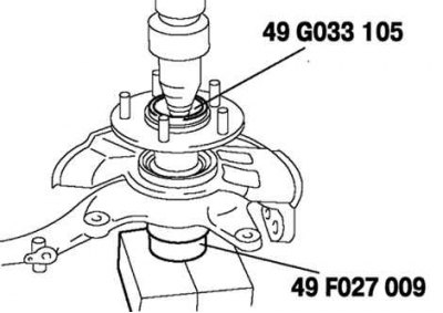
Fig. 3.114. Installing the hub
Using special tools, install the hub (fig. 3.114).
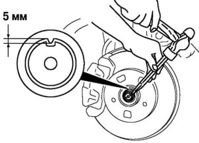
Fig. 3.115. Installing a new hub lock nut
Install a new lock nut and secure it as shown in Figure 3.115.