


Remove the anti-lock brake system sensor.
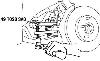
Fig. 3.126. Removing the ball joint of the steering rod end
Using a special tool, remove the ball joint of the steering rod end (fig. 3.126).
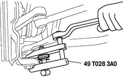
Fig. 3.127. Removing the ball joint of the lower rear arm
Using a special tool, remove the lower rear arm ball joint (fig. 3.127).
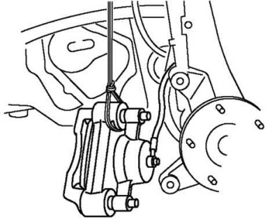
Fig. 3.128. Removing the rear brake caliper
Remove the rear brake caliper and hang it on a wire (fig. 3.128).
Caution! Sharp edges on the coupling shaft may cut or puncture the seal. Use caution when separating the coupling shaft from the transmission.
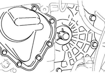
Fig. 3.129. Installing a special device for holding the axle gear
Pull the connecting shaft straight out.
Install a special device to hold the axle gear after removing the connecting shaft in the gearbox.
Remove and install the remaining components in the reverse order of removal.
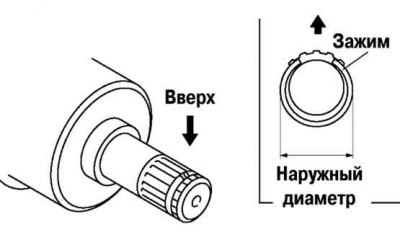
Fig. 3.130. Installing a new clamp on the connecting shaft
Before installation, place the new clamp on the connecting shaft with the slot facing up (fig. 3.130).
After installation, measure the outside diameter.
If it exceeds the norm, repeat the installation using a new clamp.
Maximum outside diameter: 31.2 mm.