


Disassembly
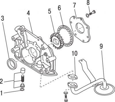
Figure 3.17. Oil pump parts: 1 – retaining ring; 2 – pressure regulator bypass valve; 3 – oil seal; 4 – pump body; 5 – internal gear; 6 – external gear; 7 – lid; 8 – screw; 9 – oil receiver; 10 – gasket
Loosen the screws securing the rear cover of the pump and remove it (figure 3.17).
Remove the gears from the pump housing. To do this, you can turn the housing over so that the gears fall out on their own.
Clamp the pump in a soft jaw vice and remove the retaining ring, plug, pressure regulator valve plunger and spring.
Examination
Wash the pump parts in solvent.
Check the parts for signs of wear, cracks and other damage.
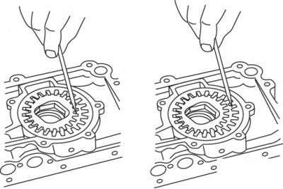
Figure 3.18. Checking the clearance between the surface of the teeth of the internal (A) and external (B) gears and the crescent-shaped calibration insert
Check the clearance between the surface of the teeth of the internal and external gears and the half-moon-shaped calibration insert, the clearance between the surface of the external gear and the housing, and the clearance between the plane of the gears and the mating surface of the housing cover (figures 3.18, 3.19, 3.20).
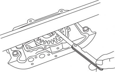
Figure 3.19. Checking the clearance between the gear plane and the mating plane of the housing cover
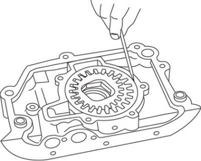
Figure 3.20. Checking the clearance between the surface of the outer gear and the housing
(Text taken from an online platform: www.mazbook.ru)
Be sure to replace the oil seal.
Assembly
Install the valve assembly with the plunger and spring and secure with the retaining ring.
Lubricate and install the gears.
Install the rear cover of the pump and tighten the screws tightly, lubricating their threads with locking compound (blocking liquid), preventing self-unscrewing.