
Disconnect the negative cable from the battery.
Remove the front wheel and tire (right).
Remove the air filter assembly.
Remove ignition coils.
Disconnect the ventilation hose.
Remove the cylinder head cover.
Remove the drive belt.
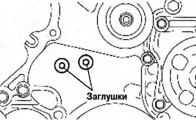
Pic. 2.237. Removing the engine front cover cap: 1 - plugs
Remove a cap of a forward cover of the engine shown in drawing 2.237.
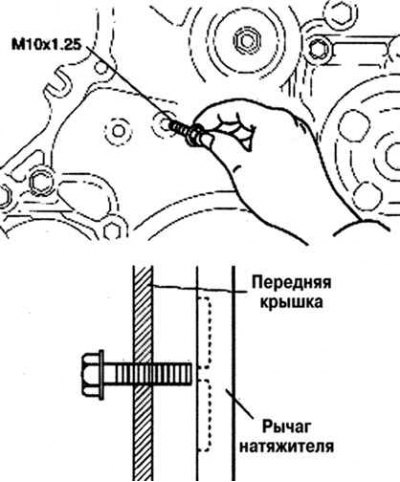
Pic. 2.238. Installing a bolt in a technological hole
Screw in the bolt by hand (M10x1.25, length 25mm or more) into the technological hole on the right side, as shown in Figure 2.238, until it rests against the tensioner lever.
Pic. 2.239. The weakening of the tension of the timing chain drive
Loosen the timing chain tension (pic. 2.239).
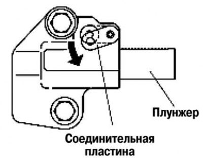
Push the chain tensioner connection plate through the service hole on the left side using a thin flat head screwdriver (precision screwdriver).
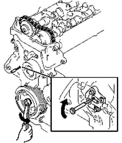
Pic. 2.240. Rotation of the crankshaft pulley
After that, with the plunger stopper released, rotate the crankshaft pulley back (counterclock-wise) (pic. 2.240).
Pic. 2.241. Tensioner lever movement
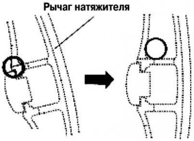
After loosening the tension of the timing chain drive, simultaneously move the tensioner lever to the position shown in Figure 2.241.
Note. The timing chain drives the tensioner arm down when the crankshaft pulley is rotated backwards (counterclock-wise).
Wrap the bolt (M10x1,25) mounted in the front cover to a position where it hits the inside of the rib on the tensioner arm.
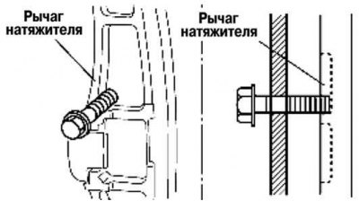
Pic. 2.242. Fixing the tensioner lever with the installed bolt
Attention! Fix the tensioner lever with the installed bolt, turn the bolt six to seven turns until it reaches the position shown in Figure 2.242.
Pic. 2.243. Fixing the camshaft from turning
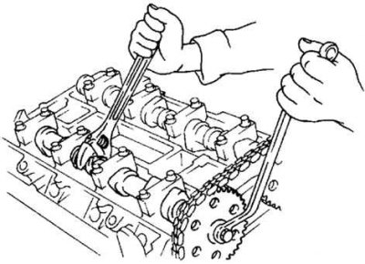
Secure the camshaft from turning by holding it with a wrench on the hexagon (pic. 2.243).
Loosen the camshaft sprocket bolt.
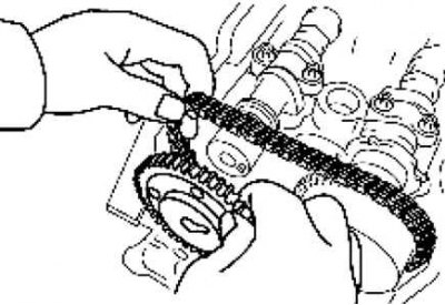
Pic. 2.244. Removing the camshaft drive sprocket from the intake side
Remove the exhaust camshaft drive sprocket with the timing chain retracted (pic. 2.244).
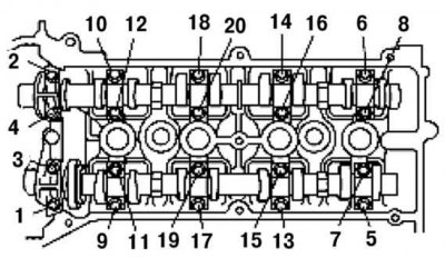
Pic. 2.245. Procedure for loosening the camshaft bearing cap bolts
Loosen the camshaft bearing cap bolts in 2-3 passes in the order shown in Figure 2.245.
Remove the camshaft bearing caps.
Remove the intake and exhaust camshafts.
Remove the valve lifters.
Select the appropriate valve lifter according to the results of the valve clearance check and install it.
Valve lifter to be selected: thickness of removed valve lifter + measured valve clearance - standard valve clearance (0.3mm).
Standard valve clearance (on a cold engine): 0.27–0.33 mm.
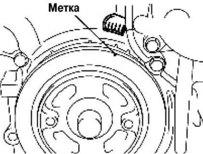
Pic. 2.246. Aligning the alignment marks on the crankshaft pulley and front engine cover
Align the alignment marks on the crankshaft pulley and the front cover of the engine, and then set the piston of cylinder No. 1 to TDC (pic. 2.246).
Install the intake and exhaust camshafts with the No. 1 cylinder piston near TDC on the compression stroke.
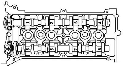
Pic. 2.247. Camshaft bearing cap positions
Install the camshaft bearing caps in the positions shown in Figure 2.247, and temporarily tighten the bolts No. 1 and No. 7 of the camshaft mounting.
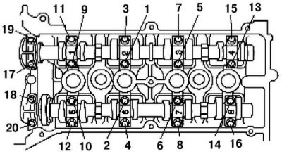
Pic. 2.248. The order of tightening the camshaft mounting bolts
Evenly tighten the camshaft mounting bolts in 2-3 passes in the order shown in Figure 2.248.
Tightening torque: 11.3 - 14.2 Nm.
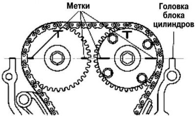
Pic. 2.249. Alignment of the alignment marks on the camshafts on the upper horizontal surface of the cylinder head
Align the alignment marks on the intake and exhaust camshafts so that they form a straight line when aligned with the top horizontal surface of the cylinder head (pic. 2.249).
Secure the camshaft from turning by holding it with a wrench on the hexagon.
Tighten the camshaft sprocket bolt.
Tightening torque: 6 - 60.8 Nm.
Remove the bolt (M10x1,25), holding the tensioner lever.
Make sure there is no slack in the timing chain, and then check that the marks on the camshaft sprocket and crankshaft pulley match.
Check the opening and closing timing of the valves by turning the crankshaft clockwise two turns.
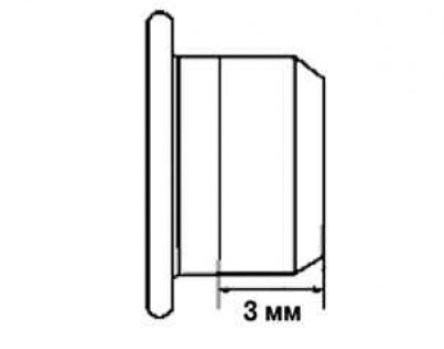
Pic. 2.250. Sealing locations
Apply silicone sealant to the plug, as shown in Figure 2.250.
Install the engine front cover cap.
Tightening torque: 3.0–5.0 Nm.
Install the drive belt.
Install the cylinder head cover.
Connect the ventilation hose.
Install the ignition coils.
Install the air filter assembly.
Install the front wheel (right).