


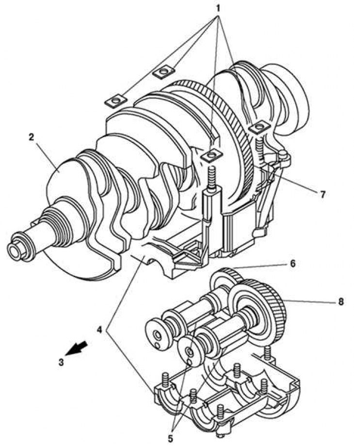
Fig. 2.12. Operating principle of the balancing unit: 1 – adjusting gasket; 2 – crankshaft; 3 – front part of the engine; 4 – balancing unit housing; 5 – counterweights; 6 – balancing shaft No.2; 7 – drive gear; 8 – balancing shaft No.1 with driven gear
Structurally, the balancing unit is installed under the crankshaft, has two balancing shafts and a housing-bed in which they are placed. With the help of balancing shafts and adjusting linings, the clearance in the engagement with the crankshaft is adjusted. The balancing shafts (No. 1 and No.2) are driven by the crankshaft pinion. Rotational motion is transmitted from the pinion, which is located between the main journals of the third and fourth cylinders, directly to balancing shaft No.1 with a driven gear. The balancing unit transmits rotation to balancing shaft No.2. The gear ratio of the balancing shaft gears was selected so that the gear rotates twice as fast as the crankshaft. The rotation speed of the balancing shaft balances the inertia force of rotation (secondary inertial rotational force) crankshaft. The balancing unit is not disassembled and cannot be repaired (Fig. 2.12).
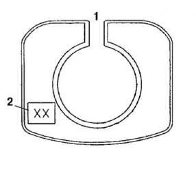
Fig. 2.13. Marking of the balancing unit adjustment linings: 1 – cylinder block; 2 – identification mark (2 digits)
Note: To adjust the clearance between the balancing unit and the crankshaft, replace the adjusting shim. There are 40 types of shims of different thicknesses. To determine the type of shim, find the marking (2 digits) on the shim (Fig. 2.13).