


Contents: Checking the brake pedal height ⇓ Adjusting the height of the brake…⇓ Checking the brake pedal clearance ⇓ Adjusting the brake pedal clearance ⇓ Checking the pedal-floor clearance ⇓ Checking the brake light switch ⇓
Checking the brake pedal height
Make sure the distance from the floor mat to the center of the top surface of the pedal support area is within the specified range.
Pedal height (control value)

Adjusting the height of the brake pedal
Loosen lock nut B and turn the bolt until it stops against the pedal.
Loosen lock nut D and turn rod C to adjust the height.
Tighten bolt with lock nut B.
Tightening torque: 9.8–14.7 Nm.
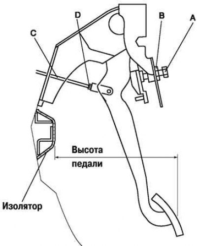
Fig. 6.15. Checking the height of the brake pedal position
After adjustment, check the pedal clearance and the operation of the brake signal (Fig. 6.15).
Checking the brake pedal clearance
Press the pedal several times to eliminate the vacuum in the system.
Remove the spring pin, make sure the holes in the fork and pedal line up, and reinstall the pin.
Gently depress the pedal by hand until resistance appears and check the clearance.
Pedal clearance: 0-3mm.
Adjusting the brake pedal clearance
Remove the spring pin and the pin with the head and hole for the cotter pin.
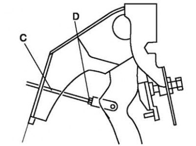
Fig. 6.16. Adjusting the brake pedal clearance
Loosen lock nut D and turn rod C until the holes in the fork and pedal are aligned (Fig. 6.16).
Install the pin with head and hole for the cotter pin and spring pin.
Tighten locknut D.
Tightening torque: 15.7–21.6 Nm.
Check the pedal height and brake light operation.
Checking the pedal-floor clearance
Start the engine and press the brake pedal with a force equal to 588 N.
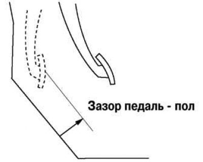
Fig. 6.17. Checking the pedal-floor clearance
Make sure that the distance from the floor panel to the center of the pedal support pad is within the standard when the pedal is pressed (Fig. 6.17).
If the distance is less than the norm, check for air in the brake system.
Minimum gap size: 68 mm.
Checking the brake light switch
Disconnect the negative battery cable.
Disconnect the brake light switch connector harness.
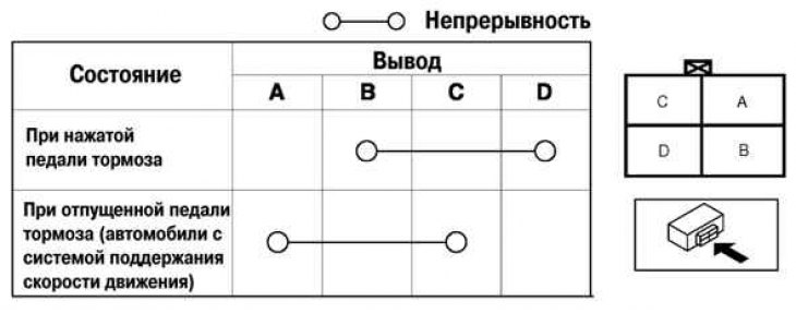
Fig. 6.18. Brake light switch test diagram
Check for electrical continuity between the terminals of the brake light switch connector (Fig. 6.18).
If not, replace the brake light switch.