


Contents: Removal ⇓ Installation ⇓
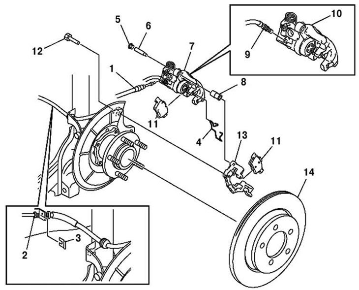
Fig. 6.51. Components of the rear brake mechanism: 1 – parking brake cable; 2 – brake line; 3 – clamp; 4 – clamp; 5 – lid; 6 – bolt; 7 – caliper, brake hose; 8 – case; 9 – brake hose; 10 – support; 11 – brake disc pad; 12 – bolt; 13 – support; 14 – brake disc
Removal
Remove the parking brake cable.
Disconnect the brake line.
Remove the brake shoe (outer side) from the support.
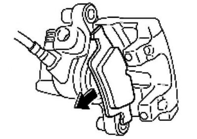
Fig. 6.52. Removing the brake shoe
Pull the brake disc pad (inner side) in the direction of the arrow to remove it from the support, as shown in Figure 6.52.
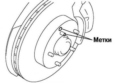
Fig. 6.53. Applying marks to the wheel hub and brake disc
Place a timing mark on the wheel hub and brake disc (Fig. 6.53).
Remove the brake disc.
Installation
Remove rust and dirt from the contact surface of the brake disc and wheel hub.
Align the marks made before removal and install the brake disc on the wheel hub.
Install the brake shoe (outer side) on the support.
Clean the exposed part of the piston.
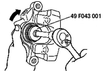
Fig. 6.54. Installing the brake cylinder piston
Slowly rotate the piston clockwise using a special device until it is completely pushed in (Fig. 6.54).
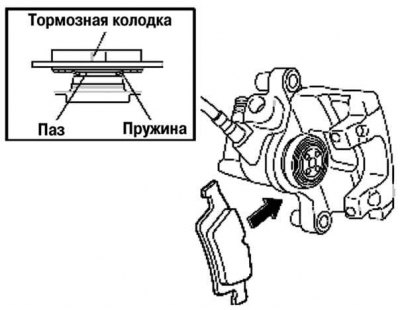
Fig. 6.55. Brake shoe spring installation diagram
Align the brake shoe spring (inner side) with the piston groove and insert it in the direction of the arrow (Fig. 6.55).
Install the brake shoe (inner side) in the support.
Install the remaining components in the reverse order of removal.
After installation, press the brake pedal several times and check the following:
- parking brake lever piston stroke;
- brake drag.