


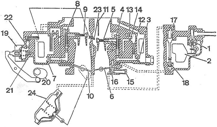
Aisan carburetor diagram: 1 - needle valve; 2 - float; 3 - main fuel jet of the 1st chamber; 4 - main air jet of the 1st chamber; 5, 9 - sprayers; 6 - 1st chamber throttle valve; 7 - main fuel jet of the 2nd chamber; 8 - main air jet of the 2nd chamber; 10 - throttle valve 2nd chamber; 11 - air damper; 12 - idle fuel jet; 13 - idle air jet; 14 - idle fuel channel; 15 - mixture quality (composition) adjustment screw; 16 - 1st chamber transition system gap; 17 - economizer channel piston; 18 - power mode economizer valve; 19 - diaphragm accelerator pump; 20 - accelerator pump drive cam; 21, 22 - check ball valves; 23 - accelerator pump nozzle; 24 - pneumatic drive of the throttle valve of the 2nd chamber.
[Original material on the website: www.MAZbook.ru]