
2. Turn on the ignition and, using a voltmeter with probes, check the voltage between each clamp and ground. See drawing. There should be 0.4 to 0.6 volts on terminal A, less than 1.5 volts on terminal B, 4.5 to 5.5 volts on terminal C, and less than 1.5 volts on terminal B.
3. Fully open the throttle and retest. There should be approximately 4.5 volts at terminal A and approximately 12 volts at terminal D. Terminals B and C should have the same voltage as given in step 55.
4. If the voltage is incorrect only at terminal D, check the installation of the throttle sensor, as described in points 6-8. If the other terminal voltages are not correct, check the resistances as given in point 8.
5. Turn off the ignition and install the rubber boot.
6. To adjust the throttle sensor, first disconnect the wiring connector.
7. Insert a 0.2 mm feeler gauge between the throttle lever and the adjustment screw, then use an ohmmeter to check for continuity between terminals D and B on the sensor. With a 0.5 mm probe inserted, there should be no contact between the clamps.
8. If necessary, adjust the position of the probe to get correct results.
9. Before installing the connector, use an ohmmeter to check the clamp resistance. With the throttle closed, the resistance between terminals A and B should be approximately 500 ohms, but with the throttle open, it should be approximately 4500 ohms. Between terminals B and C, the resistance should be 4000-6000 ohms, regardless of throttle position. Replace sensor if data is incorrect.
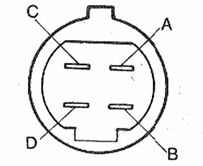
EGI Throttle Sensor Connector Clips | 
EGI Throttle Sensor Adjustment |