


Contents: Air flow meter ⇓ Throttle body ⇓ Pneumatic valve ⇓ Fuel pump ⇓ Fuel injectors ⇓ Fuel pressure regulator ⇓ Expansion tank ⇓ Fuel filter ⇓ EGI control unit ⇓
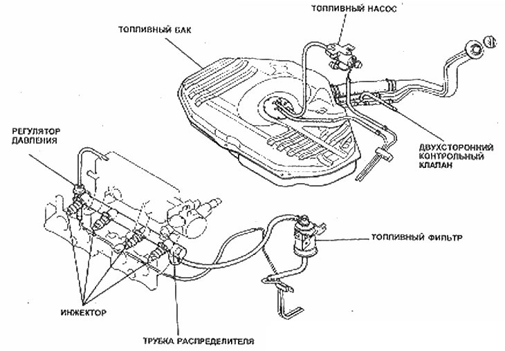
1. The EGJ system is actually a Bosch L-Jctronic fuel injection system, manufactured under license from Mazda. The main components of the system are shown in the figures and described in the following sections.
EGI system intake parts
EGI system fuel supply details
Air flow meter
2. The air flow meter measures the amount of air drawn into the engine and, via a potentiometer, converts this into a voltage signal which is sent to the EGI control unit.
3. The meter also includes an intake air temperature sensor, an idle mixture bypass system, and a fuel pump control switch.
Throttle body
4. The throttle body is located upstream of the air flow meter and is attached to the inlet expansion tank. It includes a throttle valve that is linked directly to the accelerator pedal.
5. It also includes an idle air bypass system, throttle position sensor and damper to control the throttle valve closing. The throttle position sensor sends signals to the EGI control unit.
Pneumatic valve
6. The pneumatic valve is located in the bypass hose around the throttle body. It consists of an electrically heated coil and a bimetallic plate. When the engine is cold, the valve is open and provides additional air to the additional fuel during cold starting, for a fast idle speed. During warm-up, the bimetallic strip gradually closes the valve, thus returning the engine to normal idle speed.
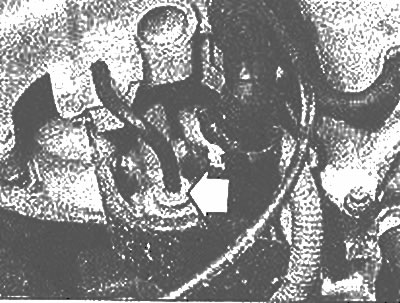
Fuel pump
7. The fuel pump is located below the rear of the vehicle, next to the fuel tank. It consists of a concentric rotor, including five rollers that move eccentrically within a gasket plate.
8. A diaphragm type muffler at the outlet end of the fuel pump absorbs pressure pulses from the pump rollers, and a control valve is also provided to relieve residual pressure within the fuel lines when the engine is continuously running.
9. The purpose of the fuel pump wiring includes a control switch in the air flow meter that always turns the pump off when the engine is stopped.
Fuel injectors
10. Fuel injectors inject fuel into the inlet ports. The amount of fuel introduced determined the gay by the period during which the injector needle valve is open and this period, in turn, depends on the signal received from the EG1 control unit.
11. All four injectors fire simultaneously once per crankshaft revolution, resulting in two injections for each 4-stroke cycle.
Fuel pressure regulator
12. If the fuel pressure to the injectors were always constant, then changes in intake manifold vacuum would deliver the wrong amount of fuel even when the injection cycle is correct. Because of this, the pressure regulator (photo) is set to keep the fuel pressure 2.7 kg/cm² higher than the pressure in the intake manifold.
Fuel pressure regulator - marked with an arrow (EGI engine)
Expansion tank
13. An expansion tank is included in the intake manifold to use acoustic wave pulses to force air into the cylinders during the intake stroke.
Fuel filter
14. The fuel filter is located in the engine compartment in the fuel supply line to the injectors. It separates out any small particles that are harmful to the operation of the injector needle valves.
EGI control unit
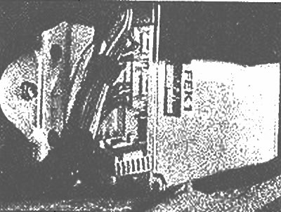
15. The EGI control unit (photo) processes information from engine sensors to control the injectors and the idle air solenoid valve. It also includes a digital check code that detects damage in the sensor circuits.
The EGI control unit is located below the instrument panel