


Use a screwdriver to pry the air conditioner switch away from the rotary ventilation grille assembly and disconnect the connector to access the screws that secure the heater control panel.
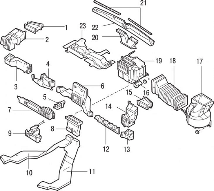
Figure 13.49. Heater: 1 – air duct No. 5; 2 – right rotary ventilation grille; 3 – air duct No. 4; 4 – fan air duct; 5 – block of rotary grates; 6 – central air duct; 7 – central rotating ventilation grilles; 8 – front heater air duct; 9 – control panel; 10 – right rear heater air duct; 11 – Left rear heater air duct; 12 – air duct No. 1; 13 – air duct No. 2; 14 – left rotary ventilation grille; 15 – air duct No. 3; 16 – additional side air duct; 17 – heater fan; 18 – air duct; 19 – heater; 20, 22 – glass heater air duct; 21 – glass heater grille; 23 – panel of rotating ventilation grilles
Remove the screws and remove the heater control panel from the instrument panel (figure 13.49).
Disconnect the connector from the heater control panel.
Disconnect the cables from the heater control panel.
Installation is carried out in the reverse order of removal. Connect and adjust the cables.
[Data provided by the website: www.mazbook.ru]