


Connect a resistor with a resistance of 12 to 230 ohms between the connector contact and the vehicle ground.
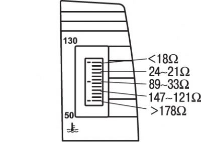
Figure 13.66. Readings of the electronic coolant temperature gauge when resistors with a resistance of 18 to 178 ohms are connected to the connector
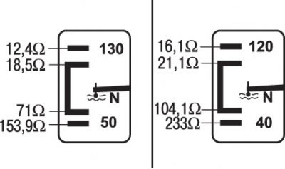
Figure 13.67. Readings of the analog coolant temperature gauge on models with a tachometer when resistors with a resistance of 12.4 to 233 ohms are connected to the connector
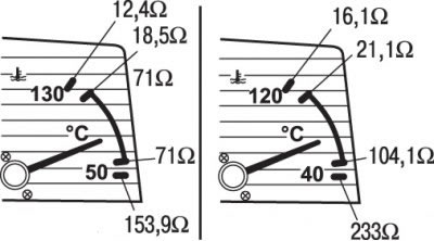
Figure 13.68. Readings of the analog coolant temperature gauge on models without a tachometer when resistors with a resistance of 12.4 to 233 Ohms are connected to the connector
Check that the wires do not touch the vehicle ground and turn on the ignition. Wait 2 minutes for the indicator readings to stabilize, then, following the figure 13.66, 13.67, 13.68, compare the actual readings of the indicator with the expected ones.
If possible, repeat the test with resistors of different resistance within the specified ranges. Before replacing resistors, turn off the ignition.
If the temperature gauge shows the maximum or minimum temperature regardless of the resistor resistance, there is a short circuit or open circuit in the sensor wires. Otherwise, incorrect readings are caused by a malfunction of the coolant temperature gauge itself.