


Warning. The models described in this manual are equipped with an airbag system. Before working in close proximity to shock sensors, steering column or front panel, disconnect the wire from the negative battery terminal, then the wire from the positive battery terminal. then wait at least 3 minutes. Accidental airbag deployment can cause injury (see paragraph 28).
Examination
1. Disconnect the wire from the negative battery terminal.
Warning. If your car radio has an anti-theft system, make sure you have the unlock code before disconnecting the battery.
2. Summit trim column (see chapter 11).
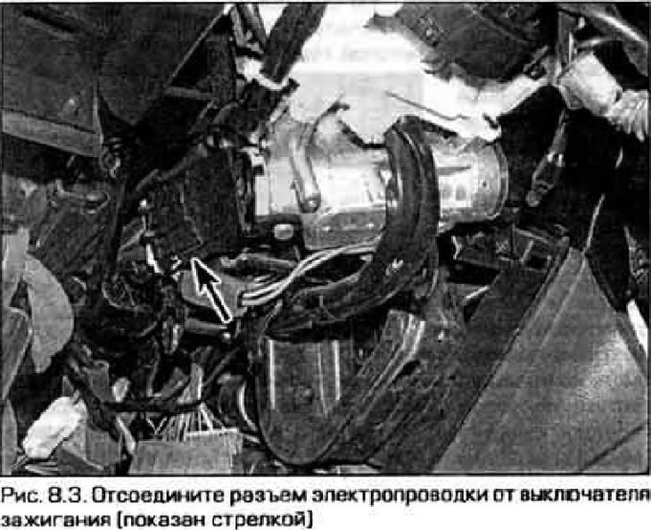
3. Disconnect the wiring connector from the ignition switch (pic. 8.3).
4. Check for contact between the switch terminals in each position (pic. 8.4).
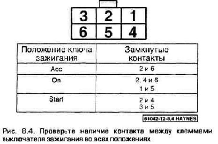
Note. When the ignition switch is set to the position "Lock" there are no contacts between all terminals of the switch.
5. If the contact between any of the terminals is not as shown in Figure 8.3, replace the switch.
6. Check the operation of the lock cylinder in each position, make sure there is no play or binding. Make sure that the position of the ignition key matches the marks on the switch body. If the lock cylinder is faulty, remove the ignition switch and replace the lock cylinder.
Replacement
Ignition switch
7. Disconnect the wire from the negative battery terminal.
Caution If your car's radio has an anti-damage system, make sure you have the unlock code before disconnecting the battery.
8. Remove the steering column trim (see chapter 11).
9. Disconnect the wiring connector from the ignition switch (see fig. 8.3).
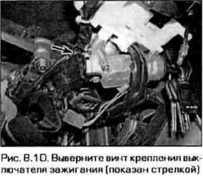
10. Turn out the screw of fastening of the switch to a steering column (pic. 8.10).
Lock cylinder
11. Remove facing of a steering column and the lower section of facing of the front panel (see chapter 11).
12. Lower the steering column (see chapter 10).
13. Disconnect the lock cable from the ignition lock (pic. 8.13).
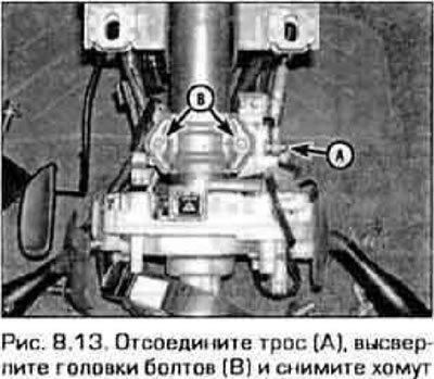
14. The lock is attached to the steering column with a clamp, tightened with two bolts with shear heads (see fig. 8.13). Drill out the bolt heads and remove the clamp.
15. Remove the lock from the steering column.
16. Clamp the lock in a vise and drill out the four pins securing the lock cylinder to the body.
17. Insert new cylinder (taking out the key) and insert four new pins of its fastening.
18. Establish the lock on a steering column, put on a collar and screw in two new bolts with shear heads. Tighten the bolts, but do not allow their heads to come off.
19. Insert the key and check the operation of the ignition switch and steering column lock. If the lock is working and the steering column is locked, tighten the bolts so that their heads are cut off.
20. The rest of the installation procedure is performed in the reverse order of removal.