


Contents: Checking voltage ⇓ Short circuit detection ⇓ Grounding fault detection ⇓ Checking the continuity of the…⇓ Detecting chain breaks ⇓ Connections ⇓
A typical electrical circuit consists of electrical components: switches, relays, motors, fuses or circuit breakers, wires, and connectors that connect the components to each other and to the battery and chassis. To make it easier to troubleshoot electrical circuits, wiring diagrams are provided at the end of this manual.
Before you begin troubleshooting an electrical circuit, first study the relevant wiring diagram and gain a complete understanding of the components involved in that circuit. Finding possible sources of a fault is easier if you ensure that other components in the circuit are working properly. If multiple components or circuits fail simultaneously, the problem likely lies with a fuse or ground connection.
Electrical circuit failures usually result from simple causes such as poor connections in connectors, poor grounding, a blown fuse, or a faulty relay. Before you begin checking the circuit components, inspect the condition of all fuses, wires, and connectors in the faulty circuit.
Use wiring diagrams to determine the order in which to test an electrical target.
Basic tools for troubleshooting electrical circuits include a tester or voltmeter (a 12-volt test light may also be used for some tests); ohmmeter (to check the circuit for broken wires): battery: jumper wire, preferably with a fuse, which can be used. to bypass the wires or electrical components being tested. Before you begin working with the instruments, study the wiring diagram to determine the points at which any measurements should be taken.
Checking voltage
A voltage check is necessary if the circuit begins to operate abnormally. Connect one lead of the voltmeter to the negative battery terminal or a good ground point. Connect the second wire to the component being tested, preferably closer to the battery or to the fuse. If voltage is present (or the control lamp lights up), this means that the part of the circuit from the battery to the voltmeter connection point is in good condition. Continue checking the chain at short intervals. When you reach the point where there is no voltage, locate the fault between the last two voltmeter connection points. Most faults of this kind are related to poor contacts.
Note: Remember that voltage on some circuits is only present when the ignition key is turned to the "Accessory" or "Run" positions.
Short circuit detection
One way to check is as follows. Remove the appropriate circuit fuse and connect the tester or voltmeter leads to the fuse terminals. In this case, there should be no voltage. Wiggle the wiring while watching the light bulb (or a voltmeter). If the light comes on, this indicates a short circuit in the circuit being tested (most often, short circuits occur in places where the insulation is worn through). In the same way, you can test a circuit by removing any of its components, even a switch.
Grounding fault detection
To check if a component is well grounded, disconnect the battery and connect one lead of an ohmmeter to a good ground point. Connect the second lead of the ohmmeter to the point of the component being tested. The ohmmeter should show zero resistance; if not, reconnect the component to ground.
Checking the continuity of the circuit
Continuity testing involves searching for and detecting breaks in the circuit. When the circuit is open, continuity is checked using a test lamp with a power source. Connect a test light to both ends of the circuit being tested. If the light comes on, the circuit is OK. If the light does not come on, then the circuit is open. This procedure is typically used to check the functionality of switches. The wires of the control lamp are connected to the terminals of the switch. When you turn on the switch, the lamp should light up.
Detecting chain breaks
The difficulty in finding breaks in the circuit is that they are usually due to corrosion of the contacts in the connectors. First, try wiggling the connectors or wiring harnesses (most often, the connection in the circuit is restored).
Troubleshooting is made easier if you remember that all electrical circuits start from the battery and go through fuses, relays, wires, connectors, and loads (pumps, electric motors, etc.), and then return through the housing to the negative terminal of the battery. Sometimes the malfunction is due to poor contact between the wires and the battery terminals.
Connections
Most vehicle circuit connections are made using multi-pin connectors. The halves of the connectors are made of plastic and are connected to each other using clamps. Sometimes half of the connectors (especially large ones) connected to each other with bolts.
To disconnect the connectors, use a screwdriver to push the plastic retainer aside and separate one half of the connector from the other. Always pull only on the connector body and never pull on the wiring harness (this may result in a broken wire or contact in the connector). Before disconnecting the connector, examine it carefully. Many connectors have multiple latches that are not always immediately obvious. All connectors consist of a half containing the pins (male connector) and a half containing the holes (female connector). These connectors are labeled accordingly on wiring diagrams, making it easier to identify the wires. Both halves of the connectors are mirror-symmetrical to each other (that is, the left side of one half of the connector is the right side for the other half). If you insert the tester probe into a female connector terminal, ensure that the probe makes good contact with the terminal. Be careful not to damage the terminal (this may lead to poor contact in this terminal, and the fault may occur later).
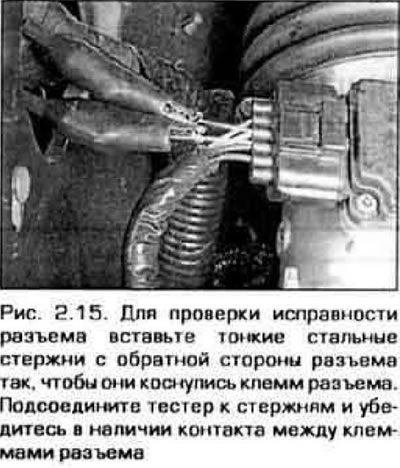
Very often there is a need to check the continuity of a circuit with a connected connector. In this case, carefully insert a straight thin rod from the back of the connector, then connect the tester to it. If you try to insert the tester probe, it may damage the connector (figure 2.15).